I wonder if someone knows how to generate floorplans in Blender from IFC-files? Preferable I would like one floorplan per storey named after the storey. I plan to use the floorplan to create separate planes for each room so it would be nice if the walls were continious even if there are doors/windows/holes in them so I select and use them to create faces. I understand that the floorplan can be complex but a good start would be to get it 1 m above each storey.
Preferable I would like one floorplan per storey named after the storey.
Do you mean 2D floorplans? With hatches, line thickness etcera? There is a whole thread about this here.
Or do you mean a seperate IfcBuildingStorey?
You want to create a plane in each room...? Are you not more versatile trying to model an IfcSpace in each room? Or better if you have existing Ifc With IfcSpaces? Because I think you mentioned in another thread you want to use it for Energy Simulations?
https://pure.tue.nl/ws/portalfiles/portal/46914631/801838-1.pdf
See page 30 for a lot of detailed information about how IfcSpace could be used.
You can also generate svg floor plans via BB:
In most project there are no spaces in the IFC I get and if they are they are not intended for energy simulations. Sometimes I can open the IFC in Revit or ArchiCAD and create rooms, but I cannot export them as a new IFC with spaces since that require a commercial license of Revit/ArchiCAD.
Thanks a lot for the link to the thread, not sure how I could miss that. I mean 2D floorplans. No need for hatches, line width or anything fancy. All I need is to be able to select lines to create faces/rooms manually in a reasonable fast way. In a perfect world the spaces would be created automatically but since the spaces are not closed this is far from trivial.
In most project there are no spaces in the IFC I get and if they are they are not intended for energy simulations. Sometimes I can open the IFC in Revit or ArchiCAD and create rooms, but I cannot export them as a new IFC with spaces since that require a commercial license of Revit/ArchiCAD.
I don't know how big your IFC models are, but is not an option to manually create the geometry in BlenderBIM and then assign an IfcSpace to that geometry? Should be fairly straighforward.
The IFC-files I get are usually between 50 and 250 Mb. Using IFC -spaces are a bit overkill since the software I use (IDA ICE) can import any closed 3D geometry as a thermal zone. Therefore just creating a floorplan for each room/thermal zone and extrude this up to floor would be fine. More complex room shapes are rather unusual.
Maybe this could work?
Make a copy of the IFC file as backup
-
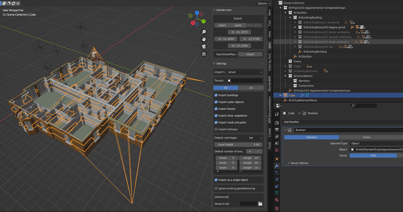
import IFC in BlenderBIM -> join all geometry in one major mesh
-
draw a huge cube over the entire IFC model
-
use the Boolean modifier to cut the cube
-
the resulting mesh -> seperate by loose parts
If the IFC file is too big you could try the same approach with a plane per building storey and join all the walls.
I just tried the method I described above
- Filtered the IfcBuildingStorey
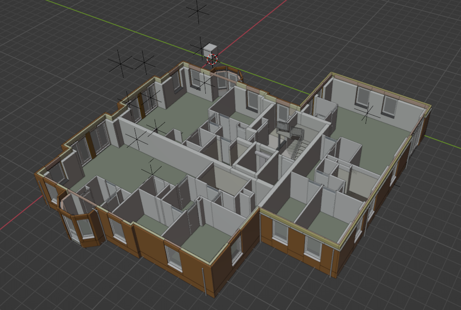
- Filtered all walls

- Joined all walls
- Modelled a mesh
- Tried the Boolean modifier with no succes :-(, I was hoping the plane would cut through all the walls neatly and I could seperate it by parts.
Does anyone know a better quicker method to do this? I never have any succes with Booleans with too complex geometry :-(
after 'joining'... try 'limited dissolve' and 'merge by distance' ?... to clean up redundant vertices.
BTW, i think this is where Topologic could come in handy. That is, creating IFCspaces from bounding ifcwalls/slabs/etc.
ping @topologic
Too bad, otherwise this was a method I thought of using. One major problem with this method is that it will have holes where there are big windows and doors but at least most of the walls would be fine.
Hello? Did someone call me? ?
Max and I have discussed this recently.
Topologic can plug in windows. Doors are a bit trickier. But the method I would try is to project everything down to 2D. Remove collinear edges. Detect rooms (Graphs and compactness help here) and extrude up
(Reposting, first attempt seem to have failed?)
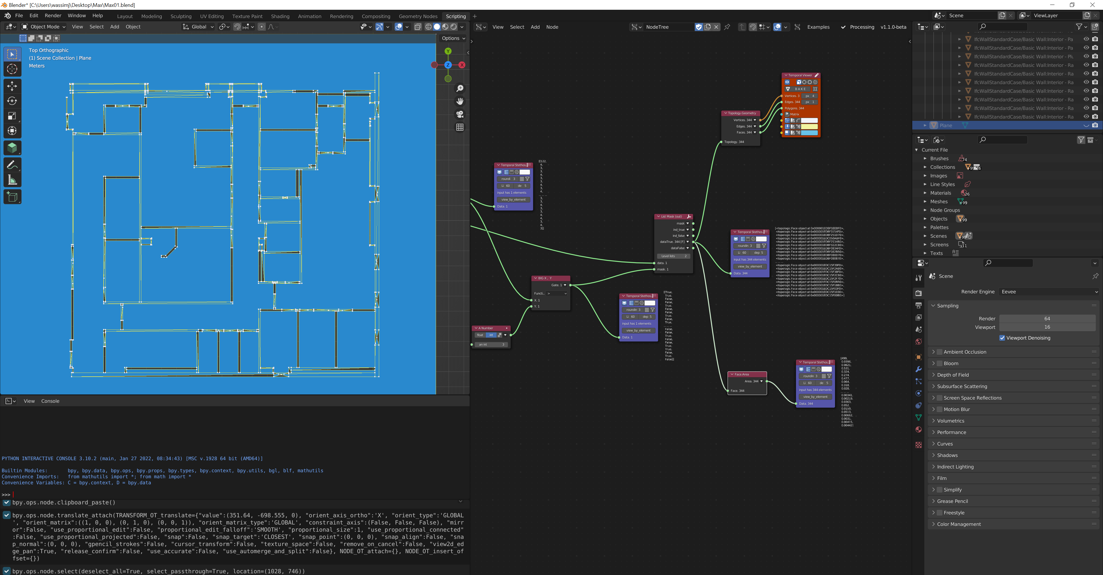
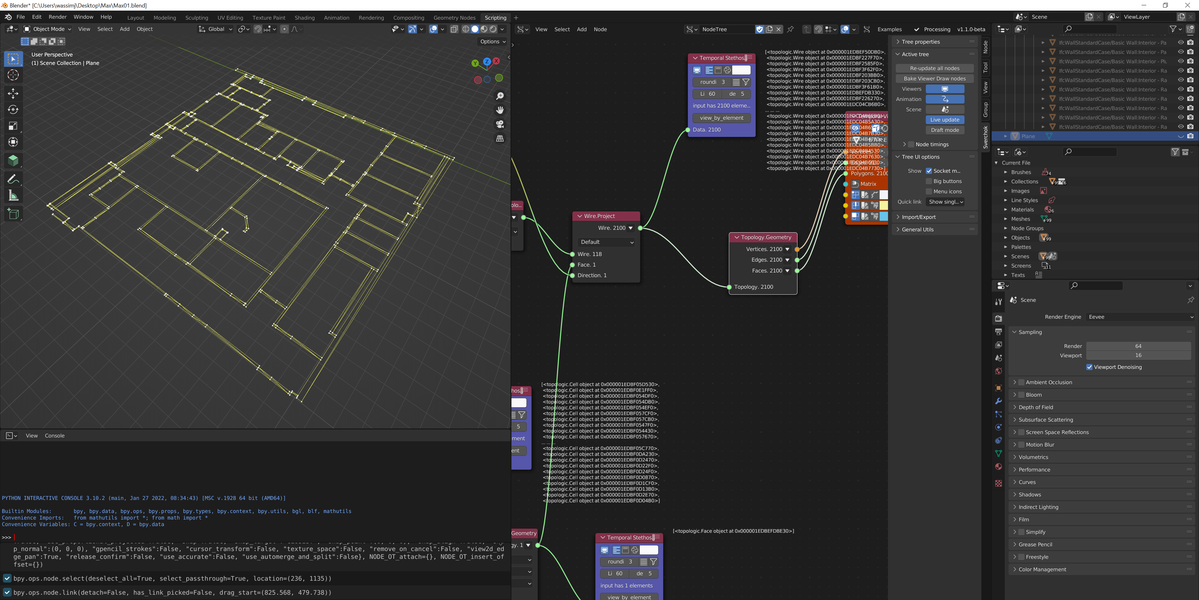
Here is my process. I used an example IFC file from BuildingSmart. I clipped to a small portion and closed off one wall to make the plan closed. Other than that, the rest is all automated. Here are the steps in general:
-
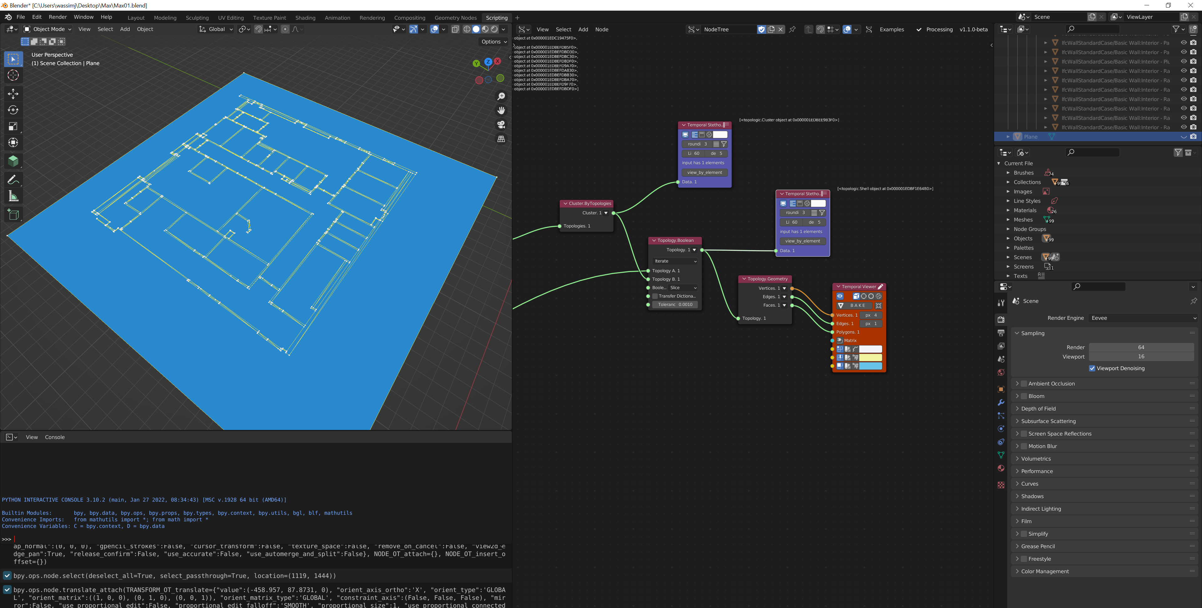
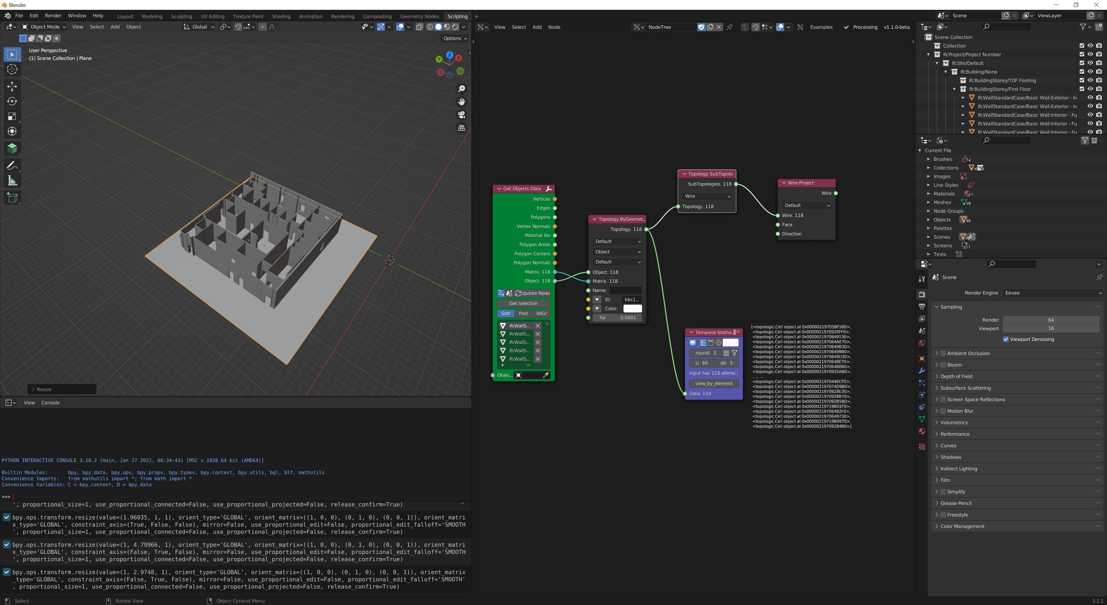
Convert all the walls to Cells
-
Get the Wires of the Cells
-
Create a base Face (manual step, but could be automated by looking at lowest Z value and bounding box and creating a large rectangle)
-
Use Wire.Project to project the wires unto the face
-
Merge all the edges of the wires into one large Cluster
-
Use Topology.Boolean to 'Slice' the base Face with the Cluster. This creates a Shell of Faces
-
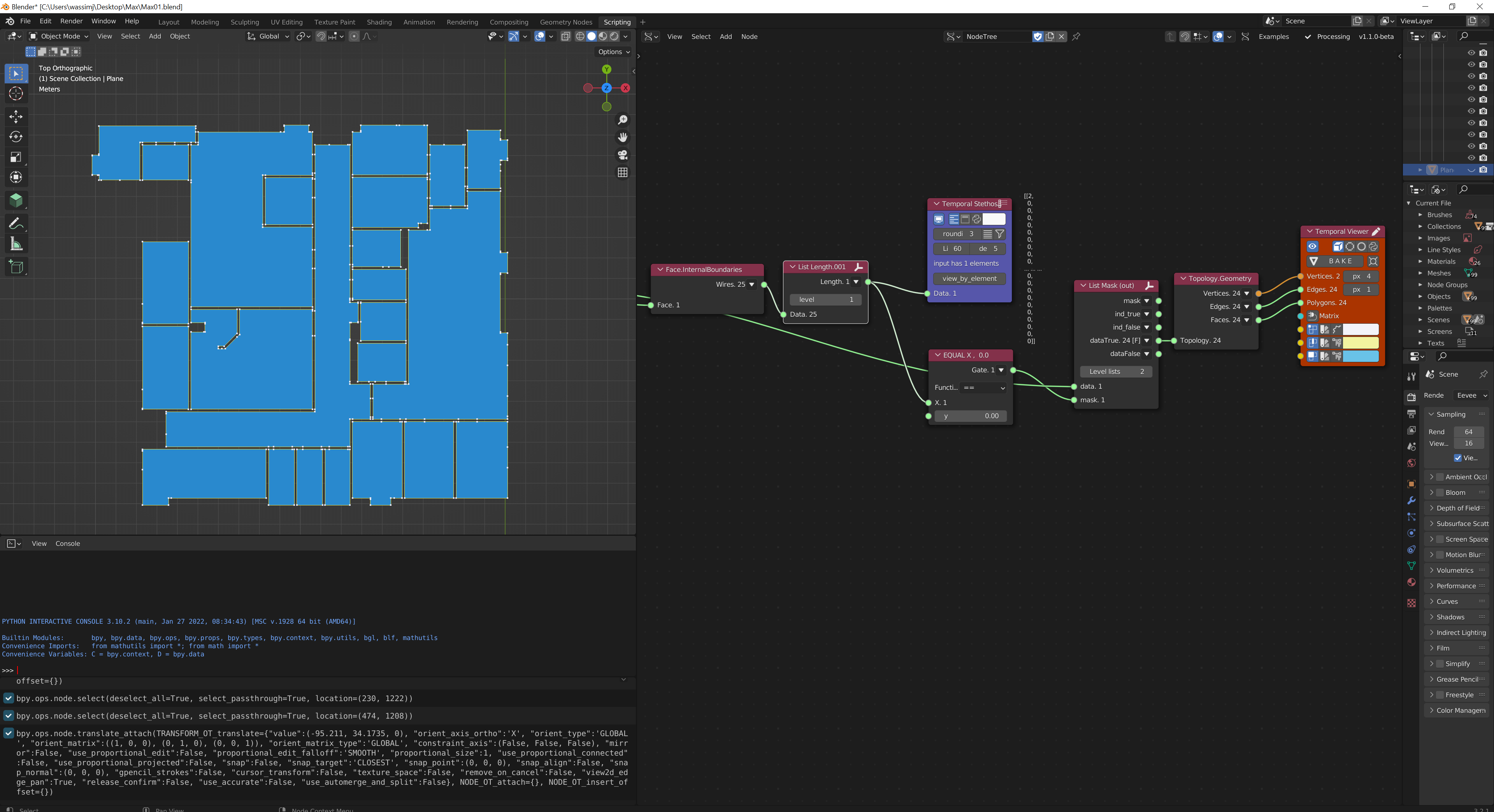
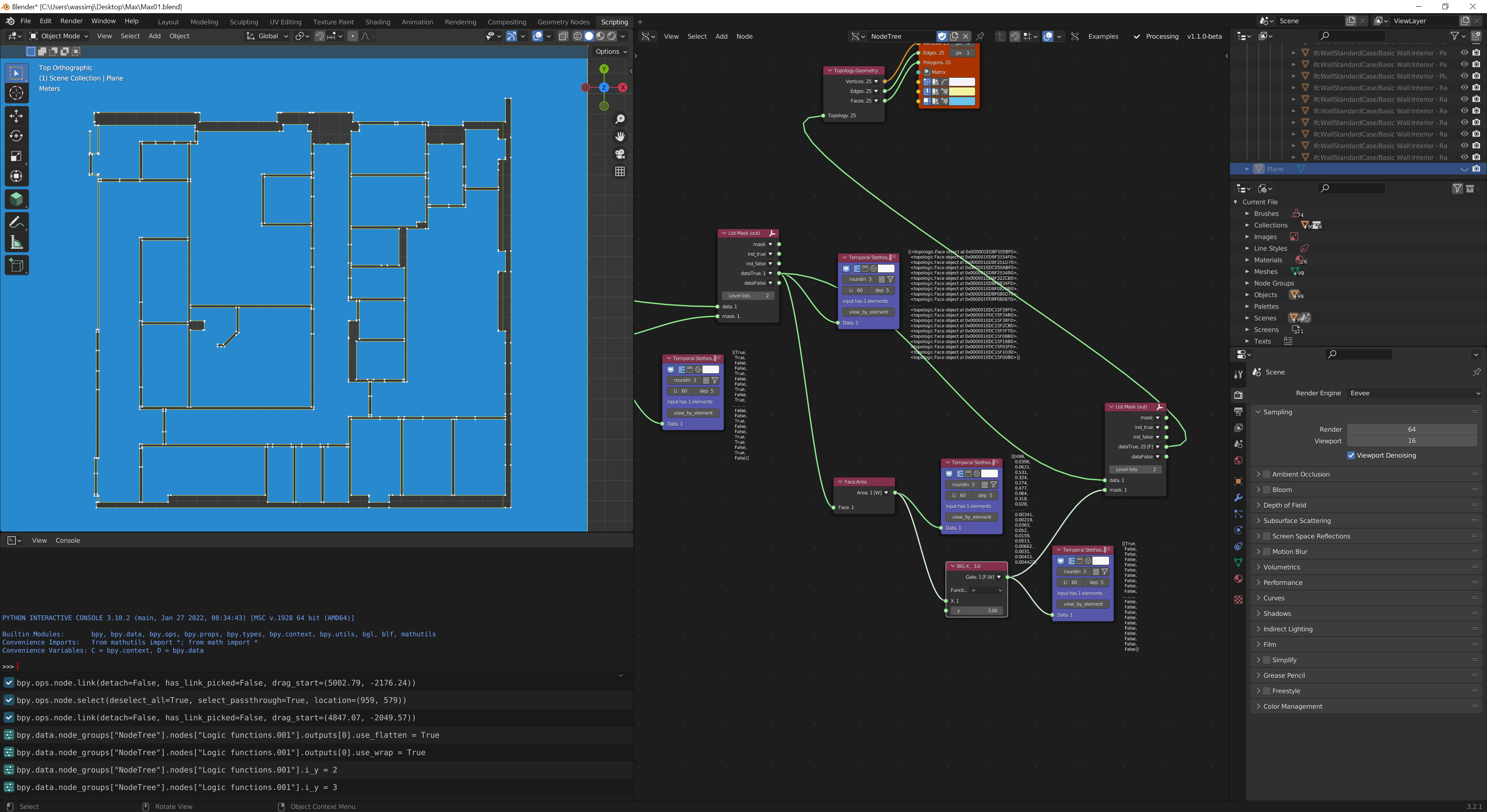
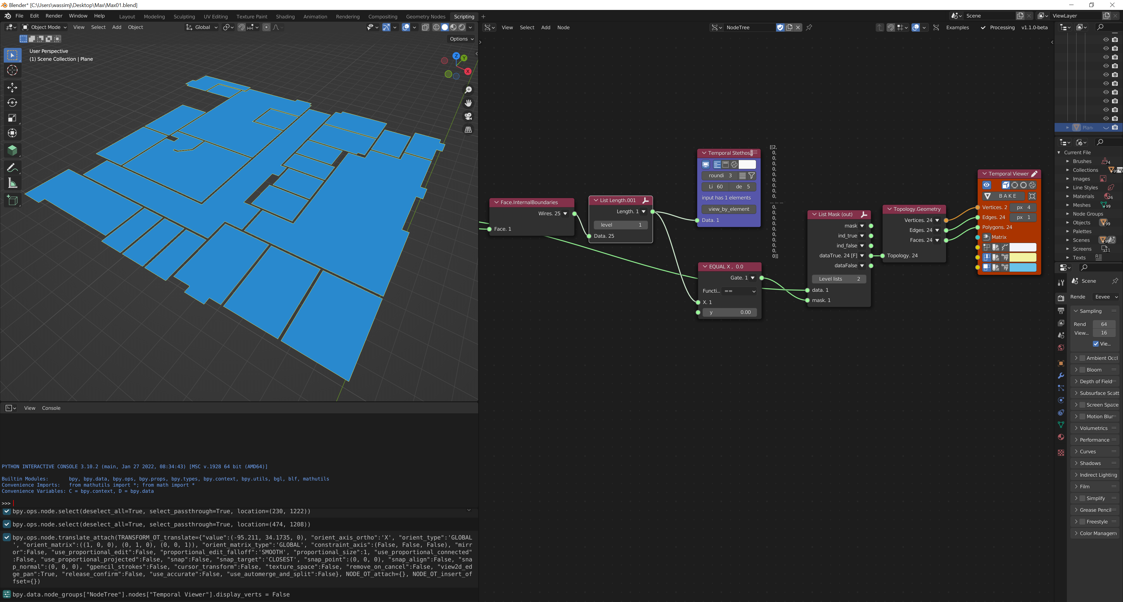
Start filtering to remove irrelevant faces:
     . Faces that are triangular

    . Faces that have an area less than a certain amount

    . Optionally, you can look at the 'Compactness' score. Walls tend to be less compact than a room

    . You can also look at the distance between parallel Edges and if you find something less than 50cm for example, that could be a wall not a room
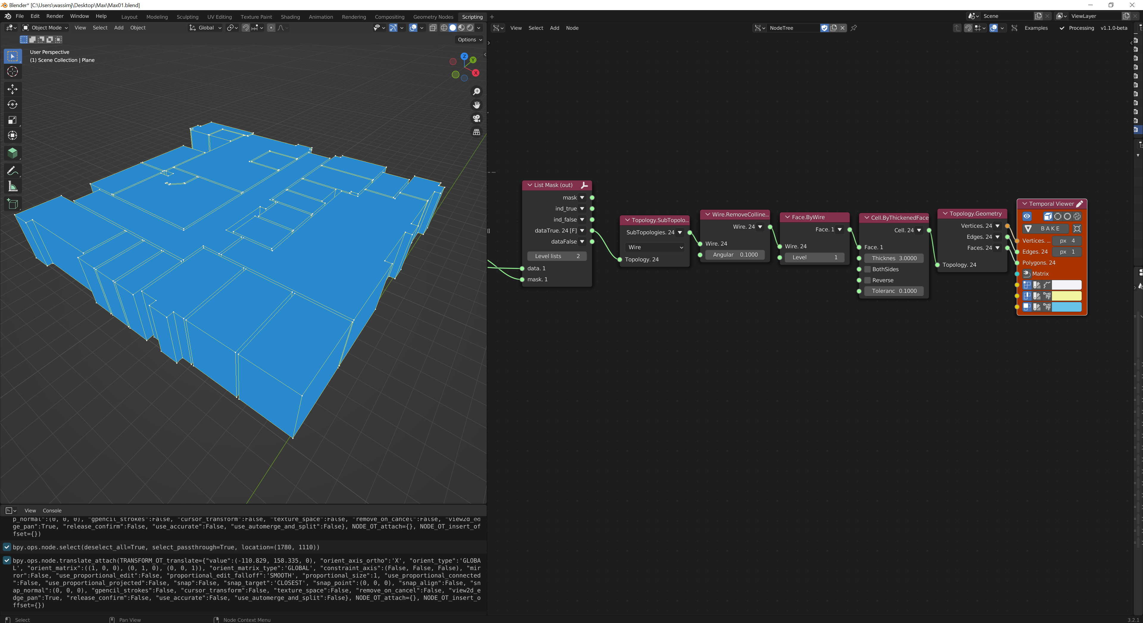
Once you have your 'Room' faces, it is a simple matter of extruding.
Cool... can you share your file? Would love experiment with it.
@theoryshaw Sure! It is attached below. It uses the latest in-house/private version of Topologic, so it might show some red nodes if you are using the public release of Topologic. If so, please be patient, I am planning to release a new version of Topologic this coming weekend.
I also forgot to add that if you know that the original Cells are all "Walls" you can use Cell.InternalVertex to get a point inside of them, then project down to the base Face and use these vertices to detect wall faces (Face.IsInside) and remove them. However, one glitch is that some of the 2D wall face got triangulated. But if you remove those first (anything triangular), the projected vertices will catch the remainder. (Just another option).
Are there any python code equivalents of creating "IfcSpaces"in each 'bounding' room/space?
@Coen said:
Are there any python code equivalents of creating "IfcSpaces"in each 'bounding' room/space?
Not sure if you’re asking me. I am not an ifc expert. I assume you can use a call to ifcopenshell api to create an ifcSpace from a boundary rep.
@topologic said:
@Coen said:
Are there any python code equivalents of creating "IfcSpaces"in each 'bounding' room/space?
Not sure if you’re asking me. I am not an ifc expert. I assume you can use a call to ifcopenshell api to create an ifcSpace from a boundary rep.
You're the geometry expert ?. You gave me the insights and made me think it's possible to do the same in python and get it exported to IFC
@Coen said:
@topologic said:
@Coen said:
Are there any python code equivalents of creating "IfcSpaces"in each 'bounding' room/space?
Not sure if you’re asking me. I am not an ifc expert. I assume you can use a call to ifcopenshell api to create an ifcSpace from a boundary rep.
You're the geometry expert ?. You gave me the insights and made me think it's possible to do the same in python and get it exported to IFC
?? The short answer is yes. One can write that whole process in python and export to an ifc file using a combination of topologic and ifcopenshell api calls.
@topologic said:
Amazing :)
There were a few issues I noted a while ago when I tried to do that in FreeCAD.
With the wall baseface removed, the Cells created would not touch each other and Topologic can't analyses the relationship between the Cells right? I can use single-lined layout with Sketch object in FreeCAD to built the Cells so all Cells are connected as a CellComplex. FC ArchWall can built all the wall upon the Sketch, no problem.
But then to truely reflect the actual internal floor plate of a room, the wall thickness should be taken out before extruding into a Cell. The process seems tedious and correlating the '2 type of Cells' becomes another problem.
@paullee said:
With the wall baseface removed, the Cells created would not touch each other and Topologic can't analyses the relationship between the Cells right?
Correct. But the OP, @Max uses (IDA ICE) which can handle these types of disjointed spaces.
In Topologic you can attempt two things:
-
Cast rays from the vertical faces and see what they hit and build graph relationships that way
-
From the start transfer a dictionary from the original wall faces to the 2D projections and next to the vertical faces of the extruded Cells. You can then connect surfaces that are across from each other that have the identical dictionary.
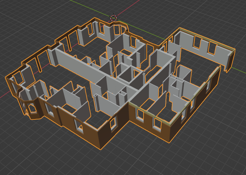
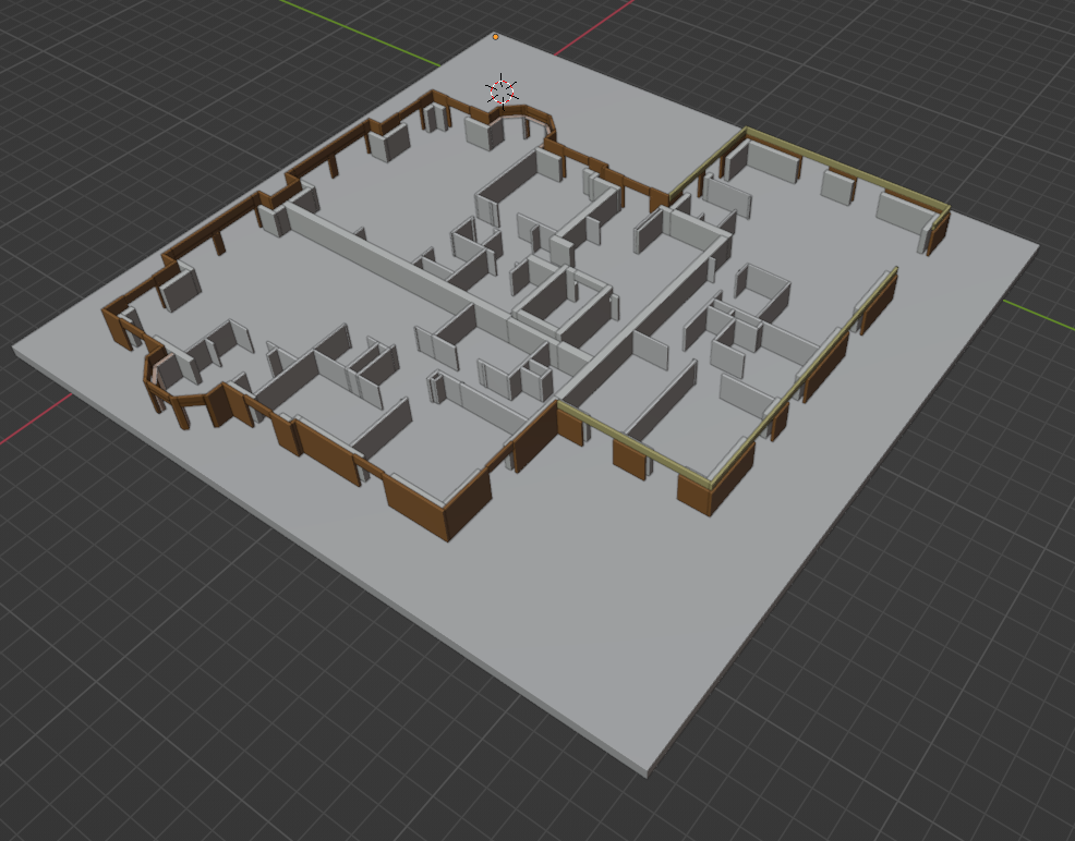
I tried an approach similar to @topologic , but with native Blender functionality
I managed to get a flat mesh from a floorplan:
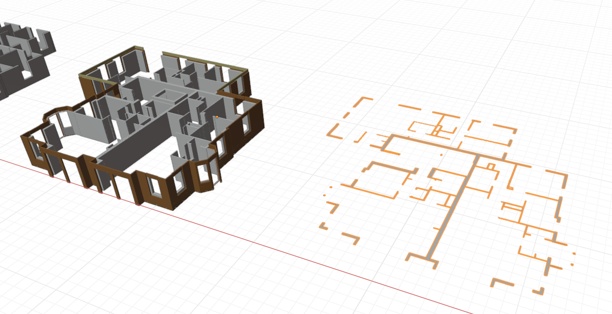
However now I am stuck, I want to close all the wall openings in this flat 2D mesh. But I can't think of a way to do this.
@Coen said:
I tried an approach similar to @topologic , but with native Blender functionality
I managed to get a flat mesh from a floorplan:
However now I am stuck, I want to close all the wall openings in this flat 2D mesh. But I can't think of a way to do this.
Use Topologic ?
One question Coen, how did you manage to get such clean 2D out of the IFC? When I tried it was a mess.
@Max
-
used BlenderBIM spreadsheet add-on to filter all the walls
-
Copy pasted the walls to a new Blender Session (Now it's no IFC anymore, just pure Blender)
-
Joined all the walls
-
Selected the faces on the top of the walls using Shift+G -> Coplaner
-
Used Shift+D to copy the faces to a new mesh.
-
Used seperate by parts. Go into Edit mode -> Faces -> A-> P -> By Loose Parts
-
Selected all the faces again and used Tris to Quads.