@bernd said:
this is what most people tell me if you ask them. But what we do if we are able to decie the orgin of a project. We just turn the CAD not the data. The disadvantage is you need to turn it often. Once the CAD and once again if you put your cuts on the drawing, you need to turn every cut on the drawing because before you only turned the CAD and not the data. Difficault to explain. I fail to explain this to others in German regularly.
interesting take, I didn't think about this
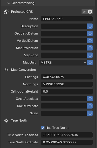
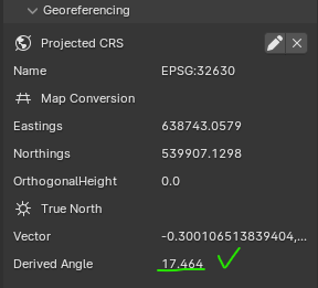
jm2c: The problem I see is if the rotation is defined by an angle. It seams Revit has to define an angle. They do not allow it by 3 points, which would be ok. Iven if you define 10 diggits, you can get problems. We have a 500 m long building, if you turn the data really by 3 points and turn it back by the angle with 10 diggits, you get differences on points 750 m away from the origin. Just very small differences, but these differences make your lines are not 100 % parallel or not 100 % 90 degree and so on. The problem is the mixture of the correct rotation defined by 3 points and the rotation by the angle with 10 diggits. If all only use the "wrong" rotation with 10 diggits everything is fine as well.
sure, for long/large structures the number of decimals matter a lot for a roundtrip approach.
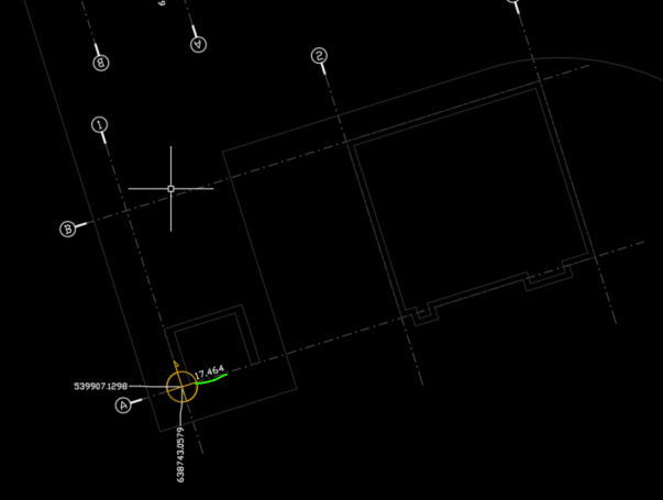
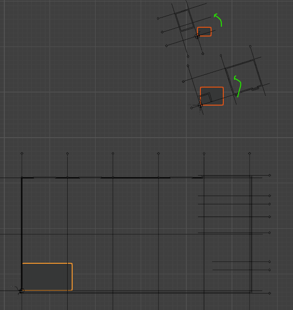
In my case the offset+rotation is not to create construction drawings, they work in local with a couple of reference points using both systems (WCS/UCS in Autocad terms) since you want to use geographical coordinates to peg the important corners (foundations, mostly) but use local coordinates within the building for instance.
In practical terms the general layout is geroreferenced, the setting out drawings (foundations, alignment, etc) show their geo-coordinates but the structures DWG like plan, elevations and sections, have local dimensioning in a gridline, not geo-coordinates.
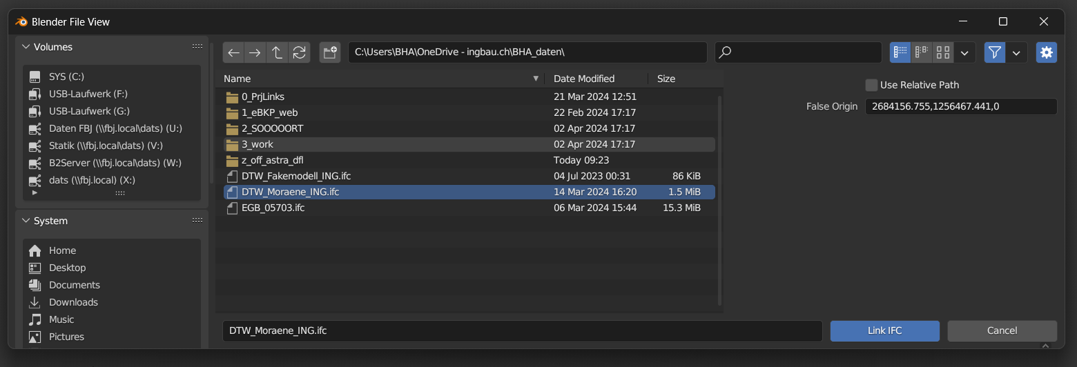
In the end I found out how to use offset/rotation using OffsetObjectPlacements patch, which does a good job for me, so happy ending :)