OSArch Community

BBIM - plumbing fittings Tee and Manifold

  1. S

    I wanted to start using IfcPipeFittingType and IfcPipeSegmentType to sketch a simple plumbing system for a bathroom, no problem with laying pipes and bends but how can I make a tee fitting? or a manifold?

    I noticed buttons to add transition and obstruction but no junction

    Do I have to create a mesh myself?

    Anybody who knows where can I find some info on this topic ?

    thanks in advance for your help

  1. G
  1. S

    Hi @Gorgious

    thanks for your link, I'd guess we are not yet at the stage where we can functionally have tees and manifolds, hopefully soon

    cheers

  1. S

    Hi, I did some MEP.

    T-Joints types I´ve created with the integrated Blender add-on "add mesh:extra objekts". After activating the add-on you can create joints in the "Addmesh-menue" (SHIFT+A Mesh/PipeJoints) after creating the mesh I´ve used the solidify modifier and apply it. (Set the Origin in the Center of a end)

    Bends90°/45°: There I´ve used the integrated Blender add-on "add curve:extra objekts". (SHIFT+A Curve/Arc). Set the radius of the bow adjust the endcontrollpoints and use the DataTab (Curve) - Geometry - Depth. (Shape:3D FillMode:Full Geometry:outer radius). Toggle with TAB in the ObjectMode-Right MouseButton: "Convert to Mesh" After that use the solidify Modifier (If the offset is in the false direction: Toggle with TAB to editmode: select all faces/points/edges open the meshTAB-normals-recalculateOutside) Set the Origin.

    Pipes: use the "pipetype-creator" edit the Profiles.

    You can take a look at my testresult (ziped .ifc)

  1. S

    hi @stefanm2

    Hi, I did some MEP.

    T-Joints types I´ve created with the integrated Blender add-on "add mesh:extra objekts". After activating the add-on you can create joints in the "Addmesh-menue" (SHIFT+A Mesh/PipeJoints) after creating the mesh I´ve used the solidify modifier and apply it. (Set the Origin in the Center of a end)

    You can take a look at my testresult (ziped .ifc)

    sure, thanks for your input, nice model

    I kind of figured it out the modelling part somehow, I was interested in leveraging on the "logical" part of BBim's MEP where segments and fittings use ports to manage a flow control, seems there were some updates recently but without supporting info I don't know how to implement it in an ordinary plumbing system as you would do in Revit for instance (I don't know much about it, more than having watched some videos on the topic)

    cheers

  1. S
  1. B

    Nice link @stefanm2 ! I've done a little bit of CFD using Autodesk CFD (apologies for swearing!) - here's one that I worked on for a water feature in Hong Kong: !

    I'm still waiting to see if BBIM will allow us to create MEP fittings and ports with Geo Nodes. I understand that Sverchok is better for linking with BBIM, but the future development of Geo Nodes within Blender looks more assured.

  1. S

    Imao the context, why and in wich case/way models and data are used, defines also the way of creating models/data, shemes, drawings. If the models getting refined (together) Owner, architect, constructor... There will be a digital twin at the end (of the construction) that can be used e.g. in smart building control, planning, simulation, FM, also destruction... In reality at the moment it's a little bit Utopia. (So one the one hand I like procedural creating, on the other I like individual processes and creating)

  1. B

    I thought I'd have a look at how Revit would size your Tee. It appears that Autodesk are linking to Energy Plus. Energy Plus is a free to use program. There is also another free program called Open Studio which is a graphical interface for using Energy Plus. I intend to look further into this but I see no reason why BlenderBIM couldn't also work with these free programs to size pipe networks. Has anyone else looked further into Energy Plus and Open Studio since I have only found them today? Open Studio is supposed to be compatible with IFC.

    https://youtu.be/ovLt4-q_UEg Link to overview of Open Studio

  1. S

    @Bedson

    I thought I'd have a look at how Revit would size your Tee. It appears that Autodesk are linking to Energy Plus. Energy Plus is a free to use program. There is also another free program called Open Studio which is a graphical interface for using Energy Plus. I intend to look further into this but I see no reason why BlenderBIM couldn't also work with these free programs to size pipe networks. Has anyone else looked further into Energy Plus and Open Studio since I have only found them today? Open Studio is supposed to be compatible with IFC.

    nice one, thanks

    at the moment I'd be happy to understand how to connect fittings, valves, and pipe segments (sanitary plumbing, not HVAC) to functionally connect source to sanitary, I can deal with arrangement and sizing, no problem (I already have plumbing 2D dwg, I need to model as IFC)

    From the little I understood of BBim's MEP/IFC is that segments and fittings have port to connect each other and the set of connected elements can be seen as a 'system'

    it would be useful to have some info on that..

    cheers

  1. S

    From the little I understood of BBim's MEP/IFC is that segments and fittings have port to connect each other and the set of connected elements can be seen as a 'system'

    Hi Steverugi,

    I haven't found a way, do "create" ports, but at the "services and systems tab" beside "0 systems Found in Project" there is the button "Load Systems"-click it- choose a system-class add it -rename, select parts "+ assign to system".

  1. S

    !

  1. S

    @stefanm2

    beautiful!

    hopefully one day I can integrate it in my workflow (modelling in IFC 2D dwg received from plumbing/electrical plans)

    from what I understand you treat objects like pipes, valves, fittings, as 3D entities and phisically connect them (not functionally) and classify them as 'system', is it correct?

    thanks

  1. S

    You're welcome... yes, thats correct

  1. B

    Nice work @stefanm2 ! How does your pipework look when BBIM is used for plans and sections? Do you use Representations for clean linework? Cheers

  1. S

    :-( didn't do it complete, therefore I had to create all systems, plans for arch, mep, do the mathstuff, create all pipes, bows, tee's... of all Nominal Sizes.... and after creating the planviews doing the linestuff in inkscape... (big part)

    Imao it's usefull to use plan/body/views with thin lines for the fitting and manifold stuff and color them in inkscape, ("theoryshaw" is the master of drawinggeneration)

  1. S

    Shit: Shift+S not Shift+A is snapping... maybe an admin can delete the original pic and place this one... thx!

    !

  1. S

    hi @stefanm2 :

    Shit: Shift+S not Shift+A is snapping... maybe an admin can delete the original pic and place this one... thx!

    any progress on MEP authoring on your end?

    I am trying to figure out the current status (240803) but it doesn't seem to be much different

    As I mentioned before I need to understand the procedure in BBIM to lay plumbing pipes (but could be electrical conduits as well) and fittings together to form a coherent system with its direction and connected parts by ports

    I can't find 'fittings' besides a FF coupling and inserting a 'bend' only allows to a fixed radius elbow, no tees or wyes, and so on

    I don't need calculation, only consistency for piping and fittings, does anybody here have more insight?

    As always, thank you for your help

    PS I gave a try at Add > Mesh > Pipe Joints, most of fittings are there somehow, did you use it to make yours shown in the image?

  1. S

    @steverugi said:

    hi @stefanm2 :

    Shit: Shift+S not Shift+A is snapping... maybe an admin can delete the original pic and place this one... thx!

    any progress on MEP authoring on your end?

    I am trying to figure out the current status (240803) but it doesn't seem to be much different

    As I mentioned before I need to understand the procedure in BBIM to lay plumbing pipes (but could be electrical conduits as well) and fittings together to form a coherent system with its direction and connected parts by ports

    I can't find 'fittings' besides a FF coupling and inserting a 'bend' only allows to a fixed radius elbow, no tees or wyes, and so on

    I don't need calculation, only consistency for piping and fittings, does anybody here have more insight?

    As always, thank you for your help

    PS I gave a try at Add > Mesh > Pipe Joints, most of fittings are there somehow, did you use it to make yours shown in the image?

    update

    hi @stefanm2 I finally sort of managed to find the way to create ports and connect pipes and fittings, still a bit funny when putting pieces together but at least I can now layout a system with relevant connections (couldn't figure out how to set the flow yet but one thing at the time..)

    thanks again for your model, I found your fittings extremely useful!

  1. J

    I finally sort of managed to find the way to create ports and connect pipes and fittings, still a bit funny when putting pieces together but at least I can now layout a system with relevant connections (couldn't figure out how to set the flow yet but one thing at the time..)

    thanks again for your model, I found your fittings extremely useful!

    Hi @steverugi if you have any notes, workflows or pointers from your explorations that you'd be willing to share, I'd be eternally grateful. Thanks for all the advice on other topics too.

  1. S

    Hi @John

    I finally sort of managed to find the way to create ports and connect pipes and fittings, still a bit funny when putting pieces together but at least I can now layout a system with relevant connections (couldn't figure out how to set the flow yet but one thing at the time..)

    thanks again for your model, I found your fittings extremely useful!

    Hi @steverugi if you have any notes, workflows or pointers from your explorations that you'd be willing to share, I'd be eternally grateful. Thanks for all the advice on other topics too.

    part 1: use elbow fitting to connect two pipe segments

    with two aligned segments selected create an elbow using the tool in N menu, it automatically adds two ports to the new fitting

    !

    the eye (1) is to show them, use the smiley next to it to turn them off

    the arrows (2) are to select each port and (3) to select the connected segment

    by checking the box next to 'Should Draw Decorations' you can see the flow

    !

    this elbow might be OK for electrical conduits, for plumbing I use Extra Mesh Objects, to be turned on in Preferences, more on this later where I create a 90deg elbow, assign ports to its ends and connect it to segments, cheers

  1. S

    part 2 create a system, assign parts to it

    !

    click on the arrow-down (1) icon to show the available systems or create a new one

    select 'IfcDistributionSystem' from the drop-down menu, click on the + button (2) to add one and the pencil (3) to edit its name or other attributes

    !

    select your elements to be assigned to the new system and press + (4) to add them

    !

    now that the system is created with its own elements it's easy to select it by pressing on the arrow (5) on the right of its name

    !

  1. S

    part 1 addendum

    sorry I missed the part where I show how BBIM adds a bend between two pipe segments..

    !

  1. S

    part 3 create an elbow fitting using Extra Mesh Objects' Pipe fittings

    make sure Extra Mesh Objects add-on is activated in the 'Preferences > Add-ons' , from top menu go to Add>Mesh >Pipe Joints>Pipe Elbow

    !

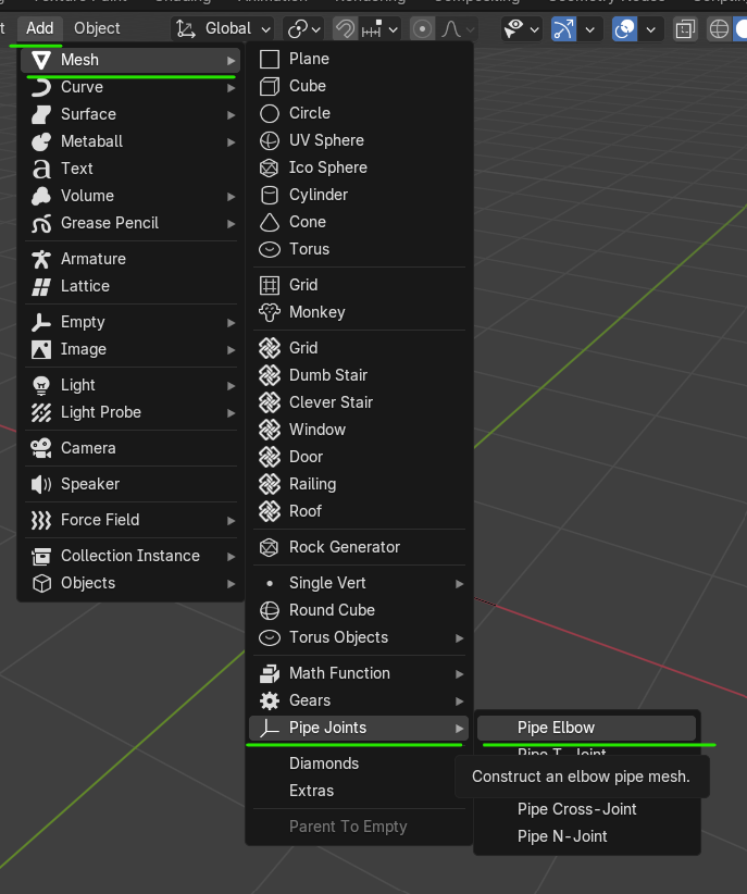
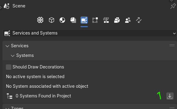
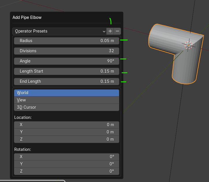
    by default it creates a 1m-45deg fitting, to edit press F9 and adjust the fields to make it smaller and 90deg, these settings can be saved by pressing the + button (1) next to Operator Presets

    !

    to add ports to the elbow it needs to be converted to an IfcPipeFitting first

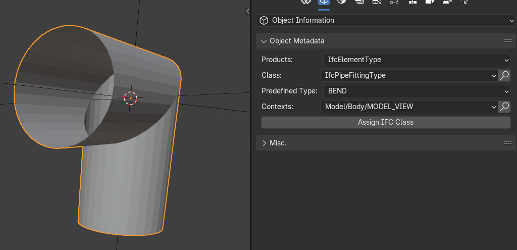
    to create a fitting type select the elbow (it's a mesh) and go to Object Information > Object Metadata and assign 'IfcElementType' to Products and 'IfcPipeFittingType' to Class, 'BEND' as Predefined Type, click on Assign IFC Class to save it

    !

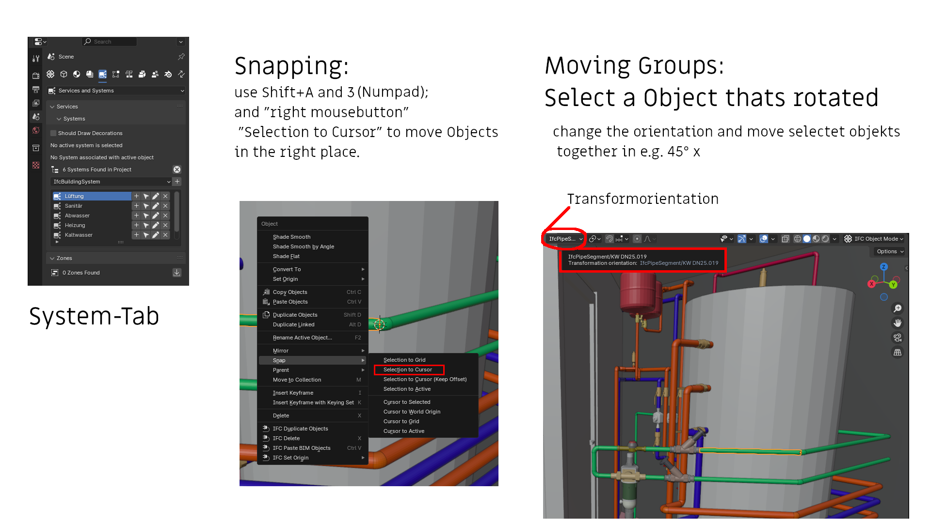
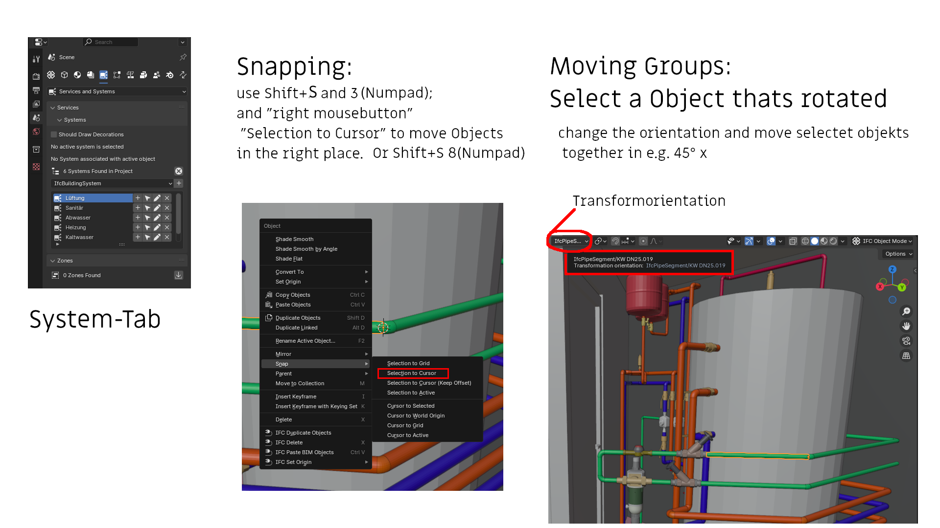
    create a pipe segment using the icon on the N menu and add the new fitting to the model, (use the cube 'Bim Tool' from the T menu, select the fitting from the top menu and click on Add or press Shift+A)

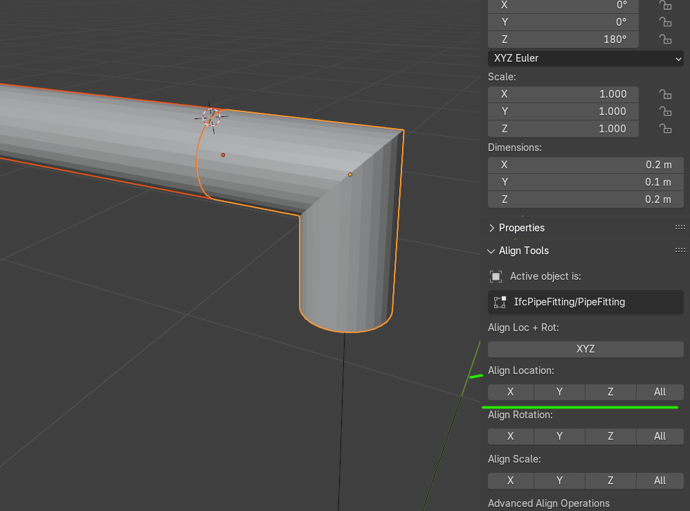
    align it to the pipe (I use 'Align Tools', activate in in 'Preferences')

    !

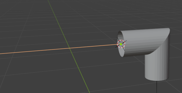
    you'd expect the elbow fitting to have two ports, one for each end, to connect it to pipe segments for instance, place the 3D cursor on one using the end of the pipe as reference, to do so:

    1. select the pipe and press Tab to show its two points entering in edit mode, click 1 to select vertices

    2. select the one next to the fitting, with Shift + S > 3 position the 3D cursor on it

    3. press Tab again to exit edit mode

    !

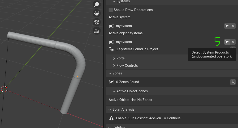
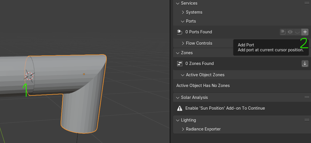
    create a new port by selecting the fitting with the (1) 3D cursor placed at one of its ends) and click on the + button (2) in the Service and Systems > Ports panel

    !

    sometimes BBIM likes playing with you and positions the 'Empty' at the model origin 0,0 (don't ask me why..) and you need to

    1. position the 3D cursor again at the tip of the pipe as indicated above

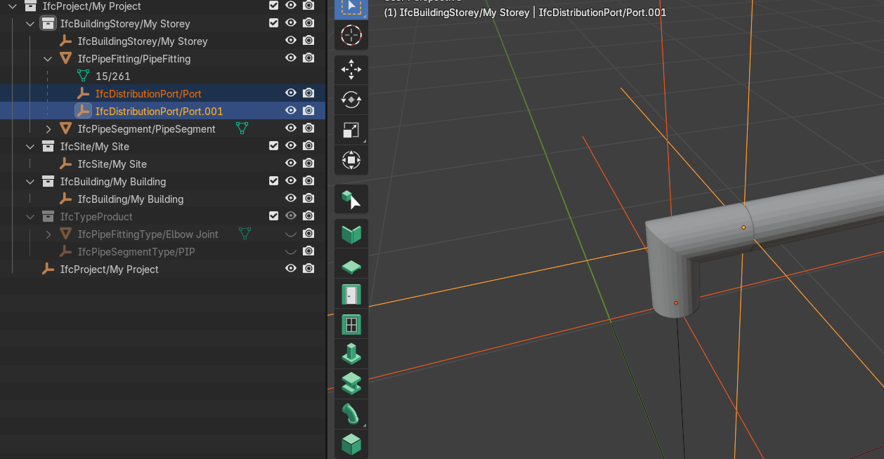
    2. select the Empty representing the port, use the Outliner and open the fitting to identify it

    3. press Shift + S > 8 to place the port/empty to the expected position

    !

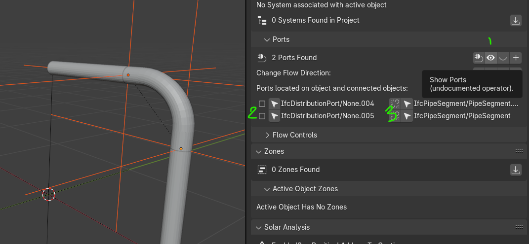
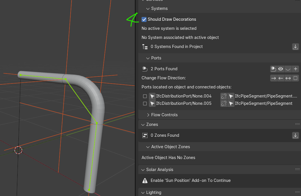
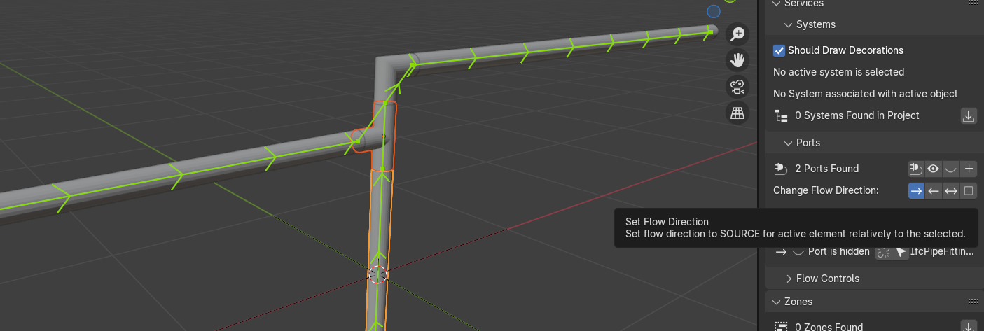
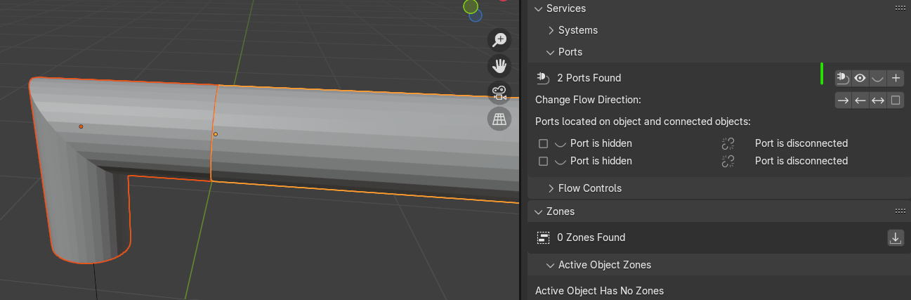
    now that the new fitting is in place with its two ports you can finally select it along with the pipe and go to the 'Ports' menu in the Services and Systems pane and select the plug (1) icon to connect them

    !

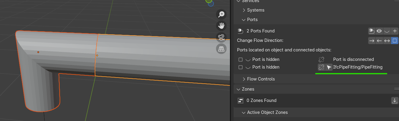
    once done you will notice that the connection is also shown in the relevant port

    !

    well, I hope you found this posts useful, please let me know

    for those out there with a better knowledge kindly do not feel shy, come forward ! :)

  1. S

    one more thing..

    selecting two elements in your system a flow can be set and visualized with the same Should Draw Decorations like this:

    !

    using the arrows a direction can be assigned, either to 'Source' or 'Sink' which (I'd guess) indicates the two ends of the system, awesome feature

    happy (MEP) modeling

Go to page:

  1. 1
  2. 2

Login or Register to reply.