OSArch Community

BBIM - plumbing fittings Tee and Manifold

  1. M

    I'm amazed you managed to work it out! Great work! Indeed we've only built the basics of MEP functionality - in theory most of the relationships are able to be manipulated manually now (but very, very, tedious and unfriendly). In terms of geometry generation, only very basic circular and rectangular extrusions are currently supported, and there is a huge amount of work still to be done on tees, wyes, crosses, and not just extruded profiles but also with thicknesses and inner diameters and so on.

    I'd say it's fun to play with, but not yet practical for a smooth workflow.

  1. J

    @steverugi thank you so much, you truly are a gentleman, and the descriptive steps are fabulous. I worked through them and have generally got it working as per your guide. However, I am experiencing some unexpected BBIM behaviour, in that when clicking on the eye icon (to show ports) it adds a new/another port (two if the pipe or fitting has 2 ports already ascribed to it) to the pipe/fitting, and continues adding them each time it is clicked. Similarly, the Closed Eye (smiley) removes ports. Sometimes the ports are added to the fitting's mesh in the Outliner, sometimes they're added at the bottom of the Outliner - I suspect the problem is operator error, so I'll continue playing with it. Below is current progress. Thanks again.

  1. S

    @John said:

    @steverugi thank you so much, you truly are a gentleman, and the descriptive steps are fabulous. I worked through them and have generally got it working as per your guide. However, I am experiencing some unexpected BBIM behaviour, in that when clicking on the eye icon (to show ports) it adds a new/another port (two if the pipe or fitting has 2 ports already ascribed to it) to the pipe/fitting, and continues adding them each time it is clicked. Similarly, the Closed Eye (smiley) removes ports. Sometimes the ports are added to the fitting's mesh in the Outliner, sometimes they're added at the bottom of the Outliner - I suspect the problem is operator error, so I'll continue playing with it. Below is current progress. Thanks again.

    you are welcome @John, illustrating procedures for me also helps streamline them, it's a mutual benefit

    I haven't personally experienced what you describe apart from finding out that BBIM at random (at least from my perspective) adds ports here and there both in number and origin

    yesterday I found out that by Shift+Ding them instead of creating new ones in the same fitting sort of eliminates the problem

    atm I am preparing a set of PPR fittings saved as IFC with their port in place as templates, once done I would hope going through erratic reactions by our beloved add-on, will substantially reduce since it will only require replicating them.

    Let's keep in touch

    happy modeling :)

    PS the issue with elements both in their container and at the bottom is temporary, when you save it to IFC and open it back it should be sorted out

  1. S

    Hi @John

    I finally sort of managed to find the way to create ports and connect pipes and fittings, still a bit funny when putting pieces together but at least I can now layout a system with relevant connections (couldn't figure out how to set the flow yet but one thing at the time..)

    thanks again for your model, I found your fittings extremely useful!

    Hi @steverugi if you have any notes, workflows or pointers from your explorations that you'd be willing to share, I'd be eternally grateful. Thanks for all the advice on other topics too.

    I am still experimenting with them, but essentially what I gathered so far is that pipes and fittings are connected by ports, assembling them looks a bit tricky at the moment, it could be because I don't do the required steps or for other reasons, but with a little patience I managed to layout a small system with all segments and fittings connected, which is something I meant to do for quite some time, here we go..

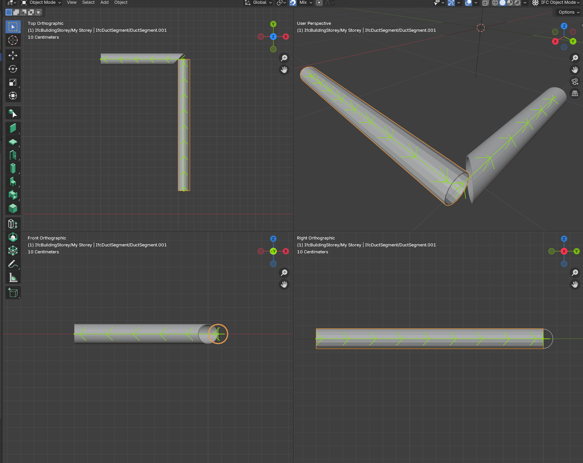
    Part 1 connect two pipe segments using the Add Bend tool, the easy one

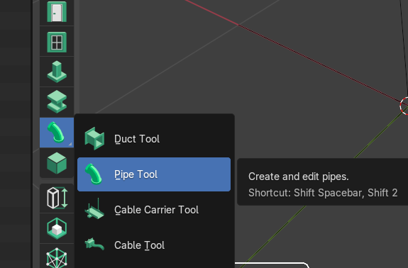
    when you create a pipe segment using the T menu (its diameter depends on the profile used to extrude it)

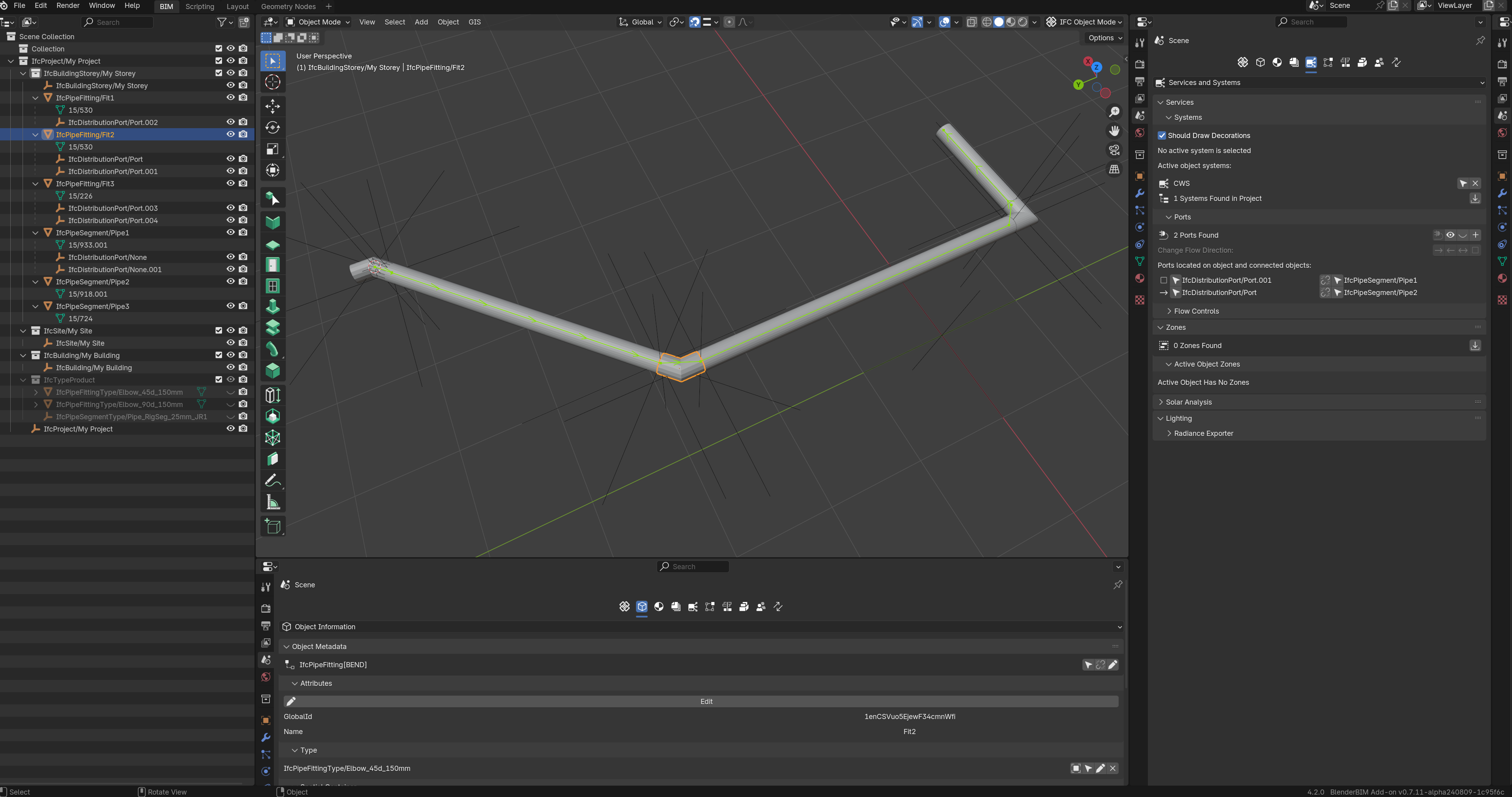
    BBIM automatically adds a port at each edge, centered on its axis

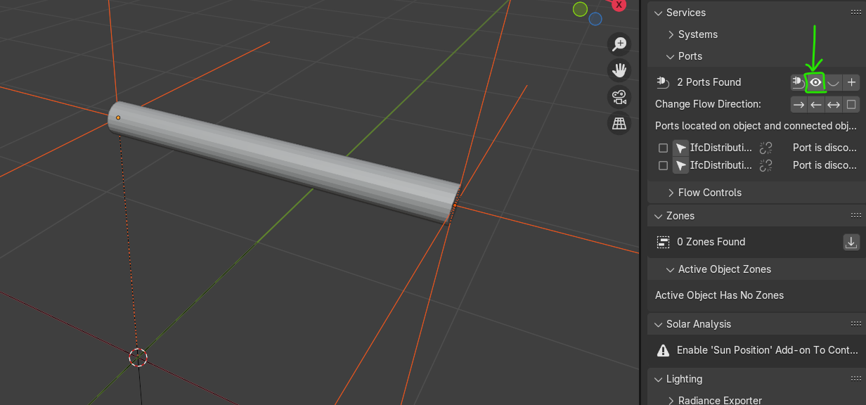
    to show the ports (represented by an empty) click on the 'eye' icon in Service and System menu, you can turn them off clicking on the smiley next to it

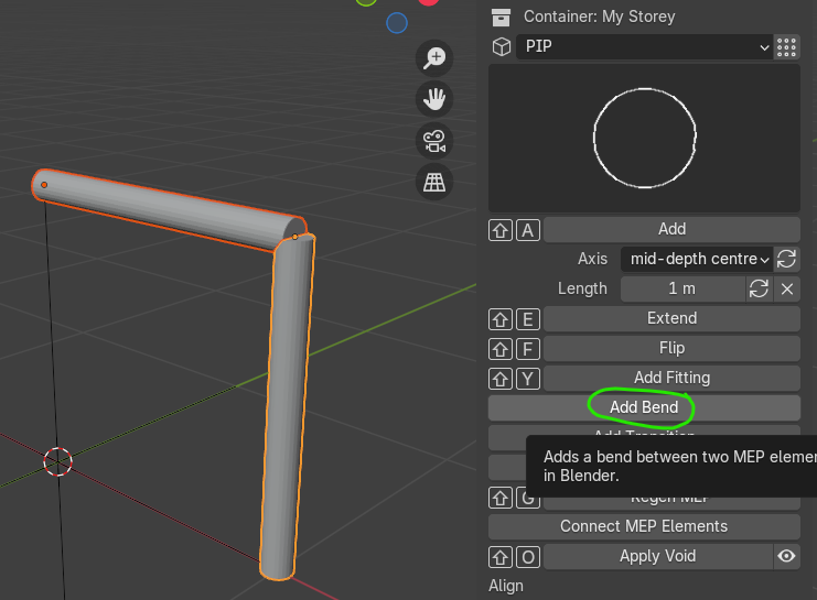
    duplicate the pipe and position it at 90deg, align both on the same axis, go to the 'tool' menu and click on Add Bend to create an elbow fitting

    once the elbow is created it too has its own ports (1 and 2) already connected to their respective segment, in my experience this could be OK for an electrical conduit, for plumbing fittings I need to use 'Extra Mesh Objects', more on this later

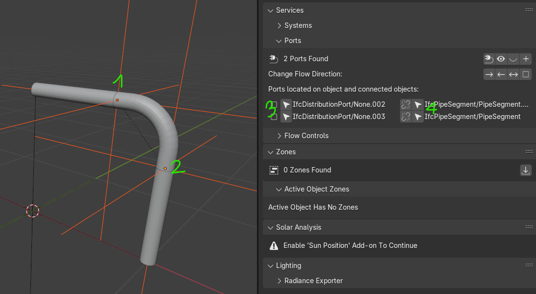
    by playing with the arrows (3) in the panel you can select the ports or (4) the connected element, also indicated on the right in writing, in this way you can walk along your system from one end to the other, useful in a more complex situation

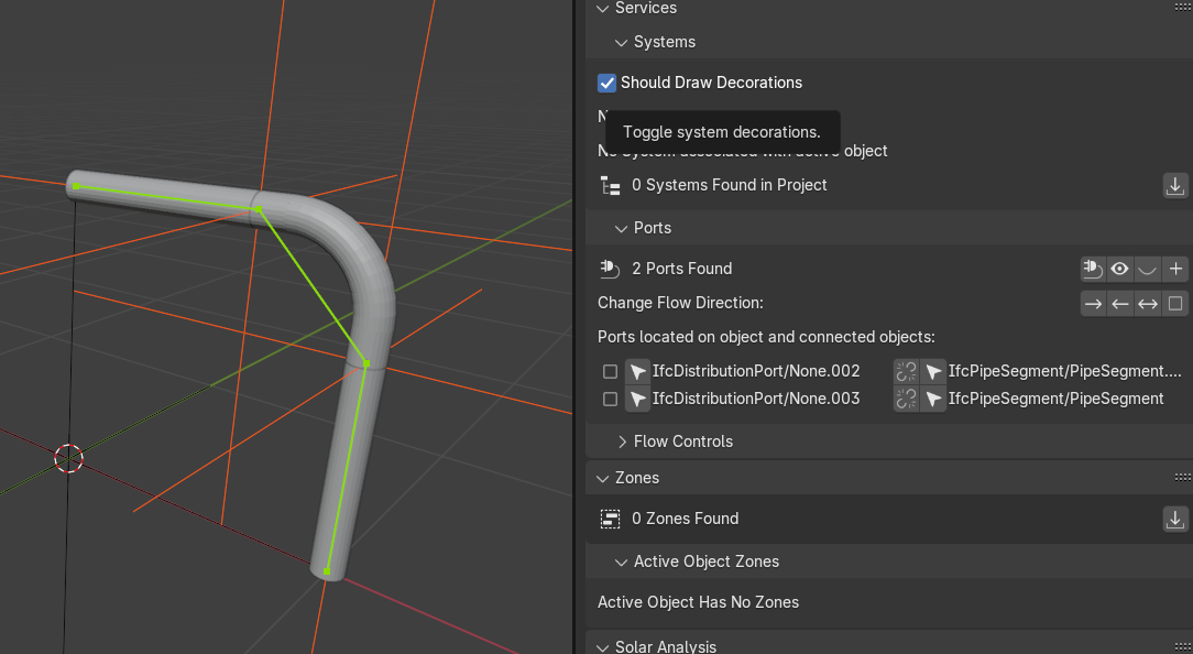
    if you toggle the box next to 'Should Draw Decorations' it shows the flow, nice feature

    in part 2 I am going to show how I created an elbow using 'Extra Mesh Objects', add ports to it, make it an IfcPipeFitting, and connect it to pipe segments

  1. S

    question

    has anyone used Bonsai/BBIM to model an electrical system? I need some help with assigning elements to a IfcDistributionCircuit to partition an IfcDistributionSystem using the UI

    as indicated here:

    thanks

  1. D

    Good day boys, just asking. At the moment, BonsaiBim have any trouble whit the bend creation betwen two pipes? or maybe im doing something wrong. Thanks in advance

  1. V

    @steverugi It is wonderful your explanations. Thanks for this.

    @Darth_Blender I have been playing with this and it is possible to do some bends but some others fail.

    I believe there are two issues that are affecting to this (Blender 4.3.2 Bonsa v0.8.1-alpha250129-871710a):

    • If you create a single segment (IfcDuctSegment, IfcPipeSegment). It does not have ports attached to it. If you create several, they all have ports.

    "

    • If you have a proper defined Segment, (for example IfcPipeSegment, including two IfcDistributionPort) and you click several times in the "eye icon" to show Ports, new ports are created. If you click the "eye shut icon" to Hide Ports. The last two are removed.

    "

    Is this intended behaviour?

    Thanks!

  1. V

    @Darth_Blender Currently if you want to do bends a possible work around is to create the segments as a polyline and then separate them so it is "easy" to get them right. Afterwards, you can move or resize the length of the segments (the fittings I believe you cannot easily).

    ex:

    "

  1. S

    hi @vdl

    I haven't used MEP in a while, did you figure out how to implement IfcDistributionCircuit in a Bonsai system? I tried several times and eventually gave up

    As soon as possible I am going to resume MEP though, it's an important part of the project quantities for me

    cheers

  1. S

    @vdl

    @Darth_Blender I have been playing with this and it is possible to do some bends but some others fail.

    I believe there are two issues that are affecting to this (Blender 4.3.2 Bonsa v0.8.1-alpha250129-871710a):

    1. If you create a single segment (IfcDuctSegment, IfcPipeSegment). It does not have ports attached to it. If you create several, they all have ports.

    2. If you have a proper defined Segment, (for example IfcPipeSegment, including two IfcDistributionPort) and you click several times in the "eye icon" to show Ports, new ports are created. If you click the "eye shut icon" to Hide Ports. The last two are removed.

    I think they are worth posting an issue about it, can you do it? thanks

  1. V

    @steverugi said:

    hi @vdl

    I haven't used MEP in a while, did you figure out how to implement IfcDistributionCircuit in a Bonsai system? I tried several times and eventually gave up

    As soon as possible I am going to resume MEP though, it's an important part of the project quantities for me

    cheers

    I have not found a way in the UI to do:

    Assignment Use Definition: An IfcDistributionCircuit should be assigned to an IfcDistributionPort on an IfcFlowController element indicating the host or origination of the system using the IfcRelAssignsToProduct relationship.

    In ifcOpenShell it looks it is possible. I am still very new to IFC and Bonsai so I am experimenting:

    
    >>> import ifcopenshell
    
    >>> from bonsai.bim.ifc import IfcStore
    
    >>> model = ifcopenshell.open(IfcStore.path)
    
    >>> 
    
    >>> distCir = model.by_type('IfcDistributionCircuit')[0]
    
    >>> flowCon = model.by_type('IfcFlowController')[0]
    
    >>> elAp = model.by_type('IfcElectricAppliance')[0]
    
    >>> disBoa = model.by_type('IfcElectricDistributionBoard')[0]
    
    >>> 
    
    >>> port = ifcopenshell.api.system.add_port(model, element=flowCon)
    
    >>> 
    
    >>> relAs = ifcopenshell.api.sequence.assign_product(model, relating_product=port, related_object=distCir)
    
    >>> print(relAs)
    
    #1230=IfcRelAssignsToProduct('10w49XroTA$xz7fQYMKXAS',$,$,$,(#105),$,#1229)
    
    >>> print(flowCon)
    
    #67=IfcFlowController('3ioiHukxT7AB0HIafZvEZF',$,'Cube',$,$,#159,#116,$)
    
    >>> print(distCir)
    
    #105=IfcDistributionCircuit('3xQ_2dzrbDUuuTKcIDpy_X',$,'ElecDistributionCircuit',$,$,$,.ELECTRICAL.)
    
  1. V

    @steverugi said:

    @vdl

    @Darth_Blender I have been playing with this and it is possible to do some bends but some others fail.

    I believe there are two issues that are affecting to this (Blender 4.3.2 Bonsa v0.8.1-alpha250129-871710a):

    1. If you create a single segment (IfcDuctSegment, IfcPipeSegment). It does not have ports attached to it. If you create several, they all have ports.

    2. If you have a proper defined Segment, (for example IfcPipeSegment, including two IfcDistributionPort) and you click several times in the "eye icon" to show Ports, new ports are created. If you click the "eye shut icon" to Hide Ports. The last two are removed.

    I think they are worth posting an issue about it, can you do it? thanks

    Sure:

    Single segment (IfcDuctSegment, IfcPipeSegment, IfcCableCarrierSegment, IfcCableSegment) does not have ports attached to it. #6073

    [Infinitely new Ports are created when clicking repeatedly times the "show Ports" button (eye icon). #6074](https://github.com/IfcOpenShell/IfcOpenShell/issues/6074 "Infinitely new Ports are created when clicking repeatedly times the "show Ports" button (eye icon). #6074")

  1. W

    I was testing Port and noticed the following:

    1 - Creating 1 Ports and saving immediately:

    Ok!

    2 - Creating 2 Ports and saving at the end:

    Oops!

    3 - Creating 2 Ports and saving immediately after each one:

    Hmm, ok!

    4 - Creating Ports with the object outside the origin point:

    Oops!

  1. V

    Infinitely new Ports are created when clicking repeatedly times the "show Ports" button (eye icon). #6074 Is already fixed! :) Nice.

  1. V

    I added two issues:

    The first one is a "feature request" in order to avoid not seeing the flow arrows for some projections and the second one I believe it is a an error as the flow direction seems to not go right when adding IfcDuctFittings

  1. V
  1. V
  1. Page 1
  2. 2

Login or Register to reply.