@magicalcloud_75
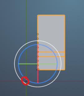
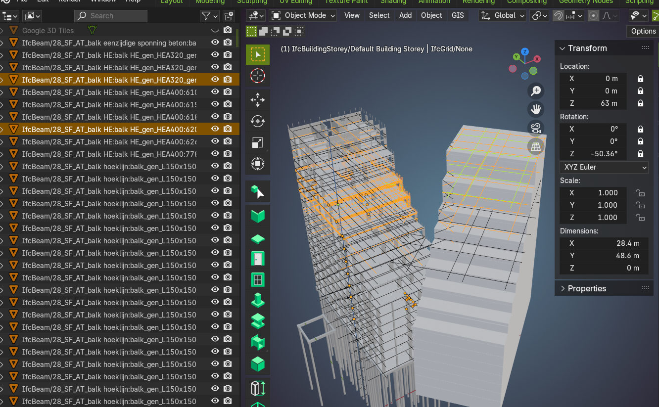
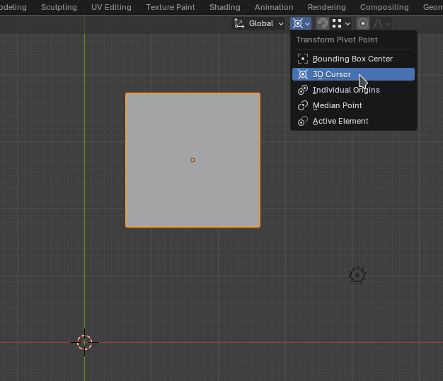
I need to rotate my building in Blender round the origin. Seems like a simple task but i can't get it to switch or use the origin as basepoint. Any idea?
Like this. I want to learn how to fix this using Blender!
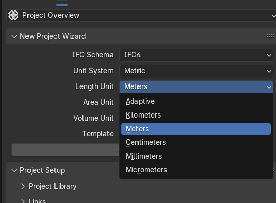
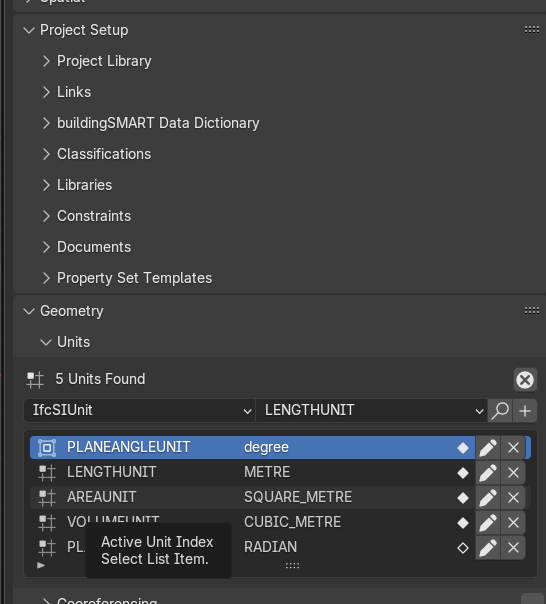
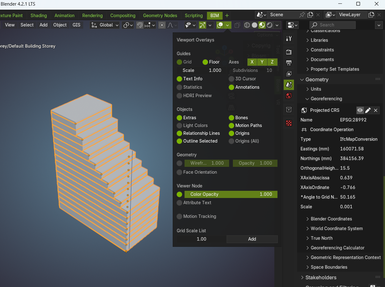
I am using georeferencing in Bonsai at work
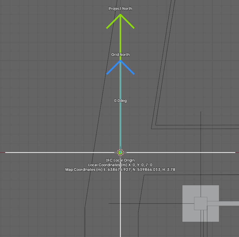
Masterplan
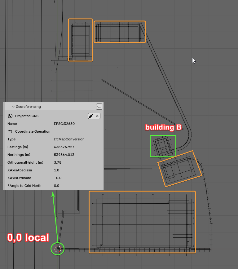
for example multiple buildings are part of the same development, here the plan with the gridlines of the buildings, the plan is oriented along the geographical north
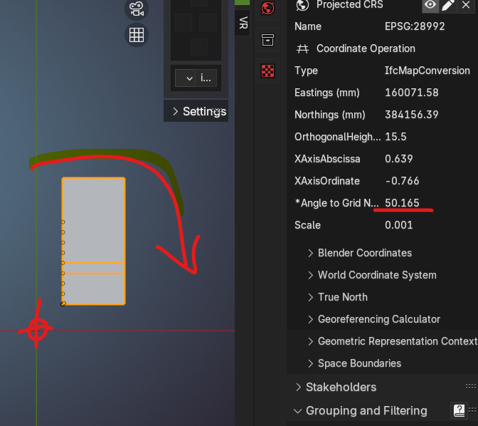
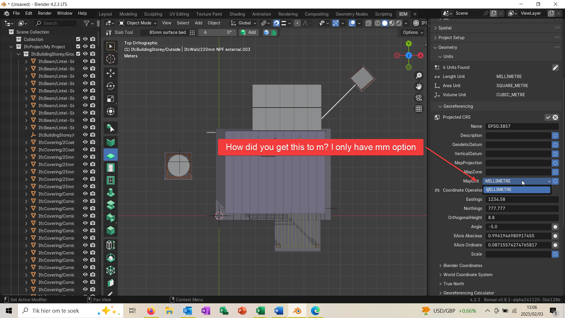
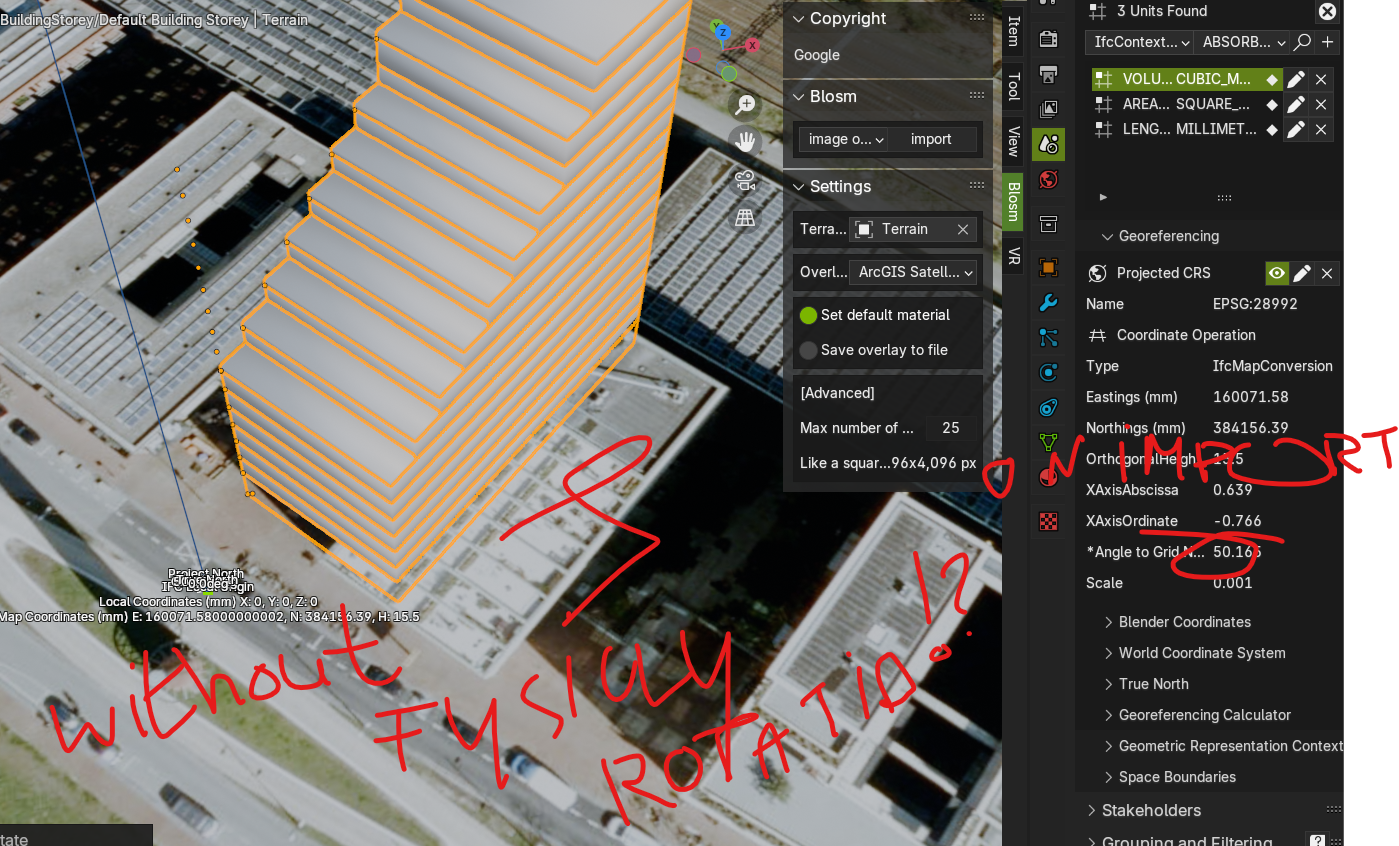
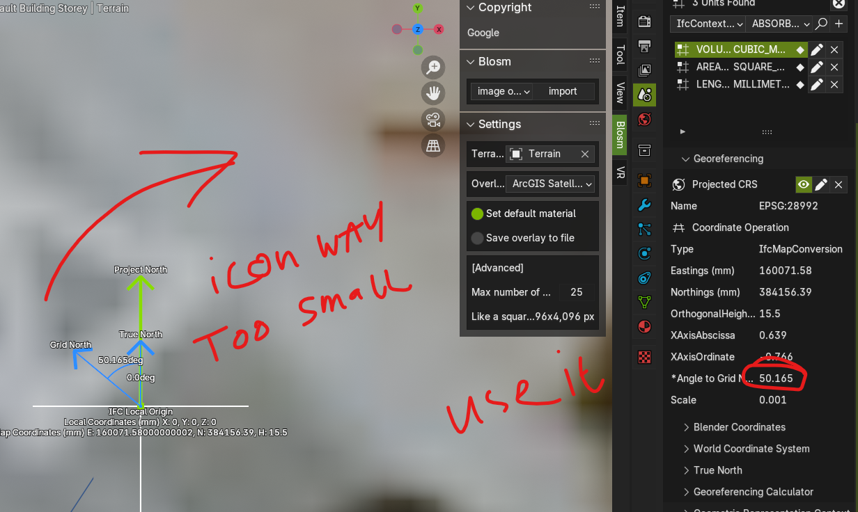
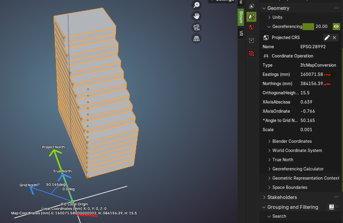
its reference point (xy = 0,0 local) has its geographical coordinates entered in the panel, along with its elevation (OrthogonalHeight)
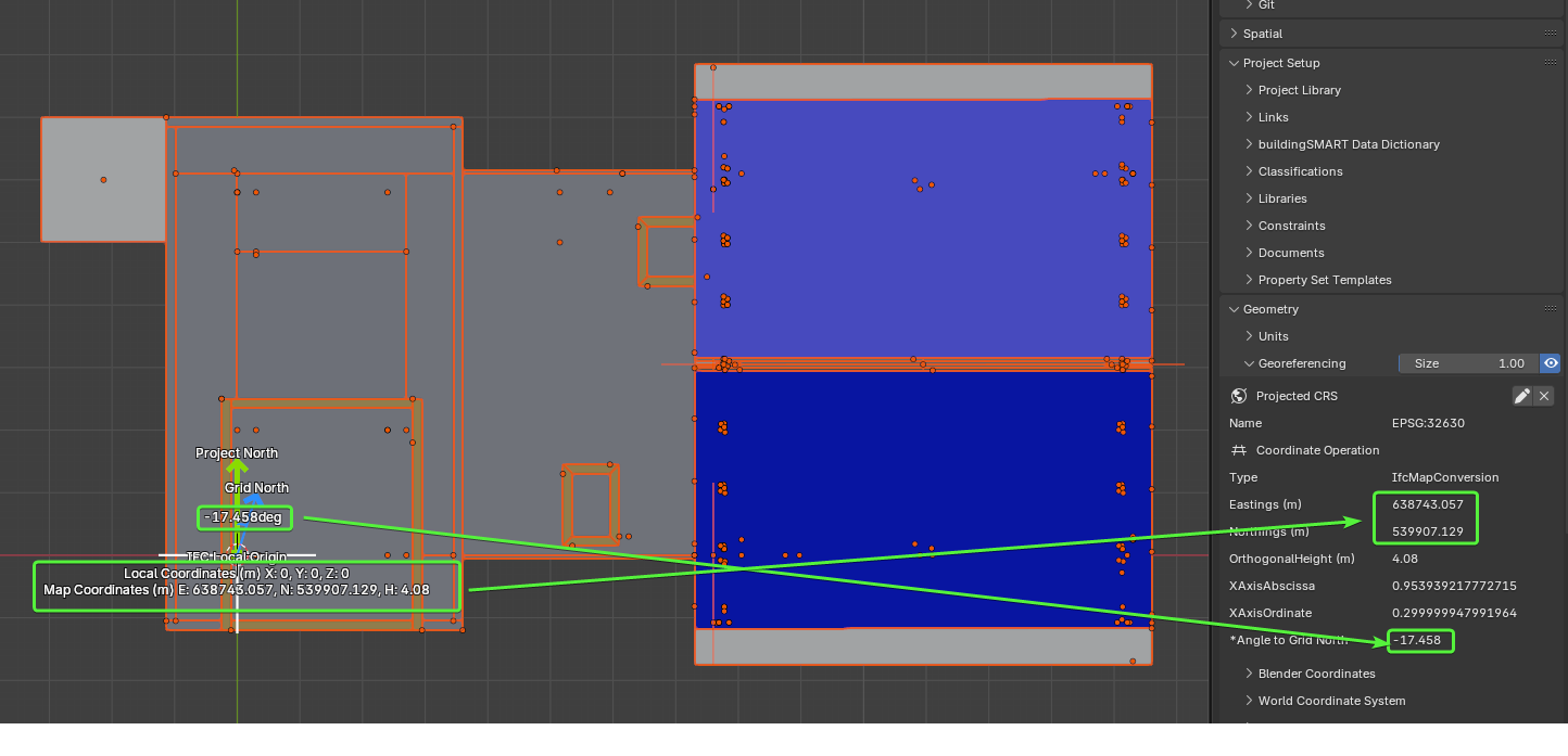
Building
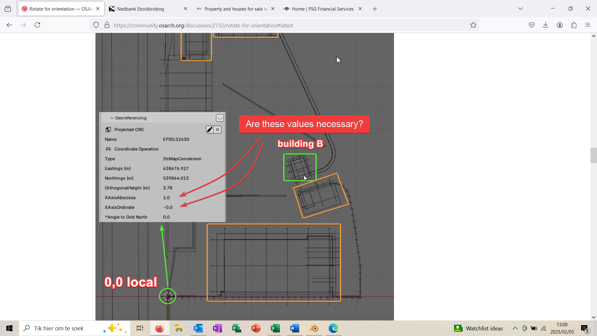
each of the buildings is in a separate model (and .ifc file) with its "local" coordinates 0,0 corresponding to a point of the same building, usually for us the intersection of gridline A and 1, building "B" for instance, with its grid lines along its xy axis.
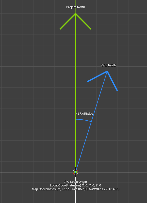
Geographically speaking the building has the origin (local 0,0) with its own xy (Easting, Northing) coordinates and it's rotated counterclockwise from the North 17.458 deg, there is also the elevation component, usually indicated in the architectural or structural drawings, something like FFL 0.00 = 4.08m
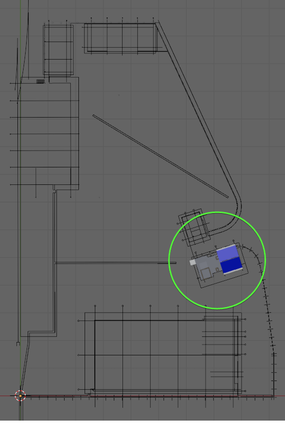
Link (AKA federate) models
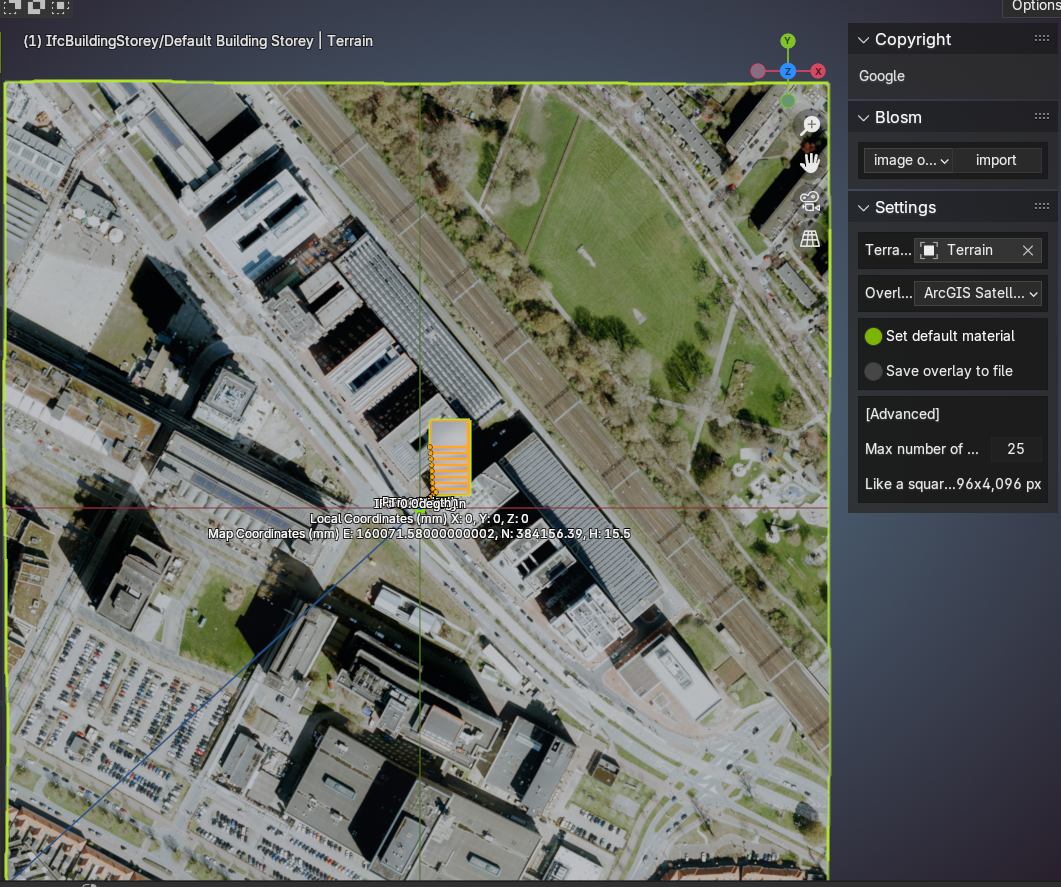
when from the masterplan I link building B here is the result:
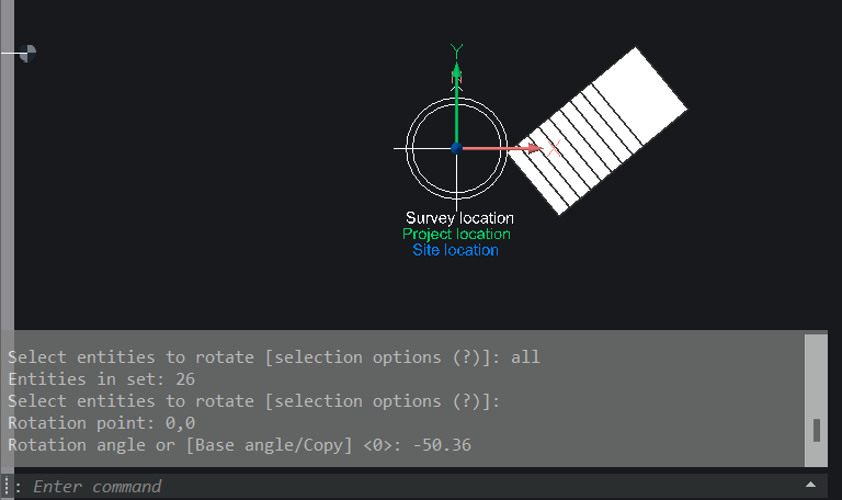
So in an nutshell the way we use georeferencing is to assign to an elected reference point in your model (datum?) both local and geographical coordinates, angle and elevation
with that the model can be plotted in a real world representation, or linked with other georeferenced models, with the right xyz shift-rotation settings
all together work in progress
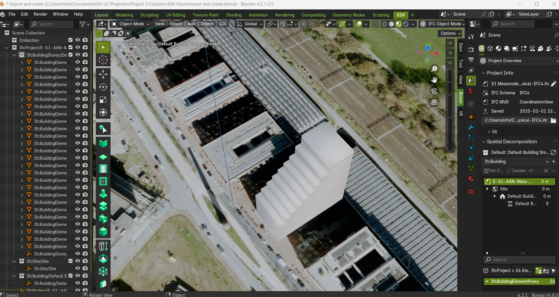
Here are the buildings linked to the master plan, there is still a lot of work to do but the result so far with other buildings is like
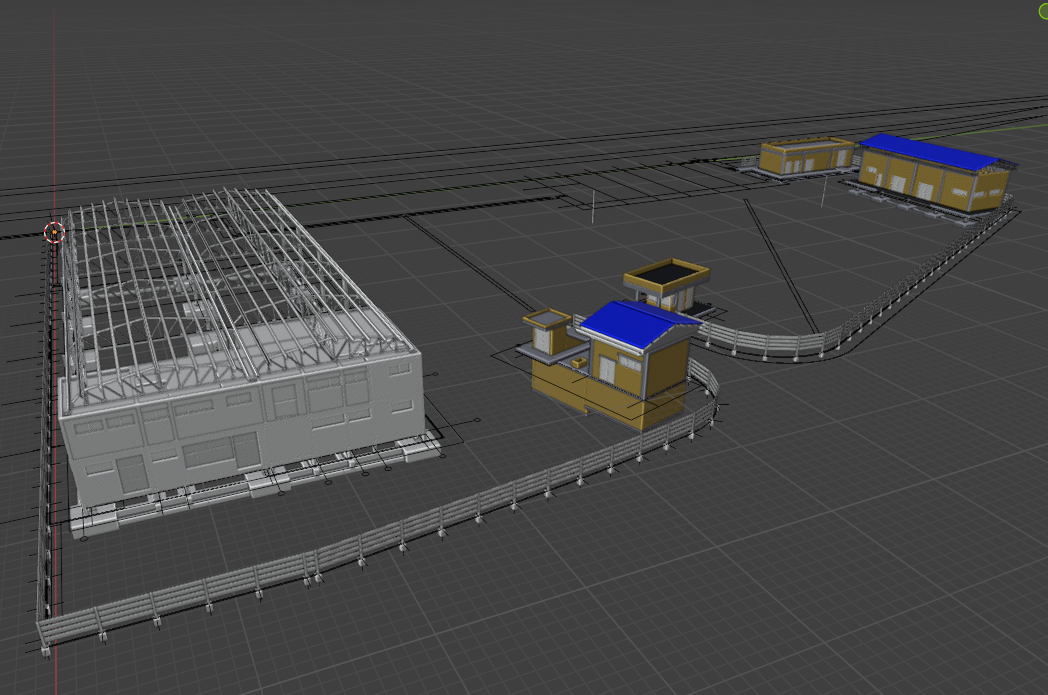
it is being done entirely in Bonsai, full IFC compliance, not bad for a FOSS software :))
I don't know if this answers to your question but maybe it could be useful, cheers and happy modeling