OSArch Community

BIM modeling using greasepencil

  1. C

    @JanF said:

    @theoryshaw said:

    @JanF your simple wall demo with the grease pencil got a good response in the Twitterverse.

    Well done!

    Hahah, cool. I added a layer for doors and windows, deciding by stroke length:

    @JanF said:

    @theoryshaw said:

    @JanF your simple wall demo with the grease pencil got a good response in the Twitterverse.

    Well done!

    Hahah, cool. I added a layer for doors and windows, deciding by stroke length:

    This is so cool. And my mind, as an architect, is blowing out. Since the new way of sketching can be found right here.

    Since i know very little about programming and python, i wonder. Does it decide door or window by stroke length? Can introducing color make it easier to define what is drawn. Chosing red is a window 55x120 , blue is a door etc..

    Might be stupid might not be. Anyhow this is so exciting..

    Cheers

  2. J

    Since i know very little about programming and python, i wonder. Does it decide door or window by stroke length? Can introducing color make it easier to define what is drawn. Chosing red is a window 55x120 , blue is a door etc..

    Might be stupid might not be. Anyhow this is so exciting..

    Cheers

    Yes, right now I made it decide by stroke length, for two reasons. First, it's faster. Switching colours/layers/etc. takes clicks, different stroke lengths are much more fluent. Second, I personally draw like this - first sketch everything with one colour and then eventually highlight important stuff/add details with other colours.

    My goal is to test out a fluent workflow (right now I do the sketch and then draw the same thing over in cad when I'm happy with the design) I hope I could sketch, get a simple model, refine, correct the sketch if something doesn't work, but keep the detail I already added.

    Apart from the increased efficiency I also hope that this way would keep the sketches present throughout the design process and therefore better preserve the design intention.

  3. J

    Do you think it would be very hard to make two ticks in the wall to define window width?

  4. J

    In the simplest form it's not hard:

    How would you go about defining the height of the opening? Also, in this version you would have to have parametric windows to make use of the width information, which is why I added only openings now.

  5. M

    This is really great stuff! How easy is it to convert Sverchok scripts into Python code that can be run as an add-on?

  6. J

    That is absolutely great!

  7. J

    @Moult said:

    This is really great stuff! How easy is it to convert Sverchok scripts into Python code that can be run as an add-on?

    Pinging @nikitron for the answer, I still haven't gotten to looking at blender plugins creation unfortunately.

    For me the biggest issue now is the lack of standard for multilayered walls and parametric door/window objects in blender, (I'm not sure what archipack does, but the pro version is not os anyway) if we agree on something in these areas we can start developing a plugin.

  8. N

    @JanF said:

    @Moult said:

    This is really great stuff! How easy is it to convert Sverchok scripts into Python code that can be run as an add-on?

    Pinging @nikitron for the answer, I still haven't gotten to looking at blender plugins creation unfortunately.

    For me the biggest issue now is the lack of standard for multilayered walls and parametric door/window objects in blender, (I'm not sure what archipack does, but the pro version is not os anyway) if we agree on something in these areas we can start developing a plugin.

    For now you can use sverchok as addon itself (node tree can be represented in 3d window panel). But it needed refactoring for scripts to go from tree. It could be possible anyway.

  9. J

    @Moult could you please split the offtopic part of this thread into a new "grease pencil bim" topic? (starting roughly with my 7th September's post)

  10. M

    @JanF all done :) Would you like admin rights, by the way?

  11. J

    Great, thanks. And sure, I can keep an eye on the forum for a bit.

  12. M

    Done - have fun!

  13. J

    Next step in grease pencil sketching to model: Snapping to predefined axes (and generating volumes)

    The user defines vectors of his axis directions, the reference lines find the closest one (angularly) and each wall snap to the direction assigned to it.

    My current concept is actually to create a set of "modules" (if you are familiar with Darktable that kind of modules I mean) - each module acts independently and can be turned on or off (sort of like adjustment layers in Photoshop, now that I'm thinking about it), it doesn't change the original geometry, but takes it as a source and creates a modified copy, this way the whole thing stays completely parametric, the only data in the file is the original geometry, the modules used and their parameters.

    Modules:

    1. GP to lines - takes GP strokes and turns them into straight lines

    2. Cleanup - takes straight lines and searches for lines with similar direction and colliding ends to turn them into a single line

    3. Axes recognition - takes straight lines and turns them into straight lines with an appropriate axis as a parameter

    4. Axes snapping - takes straight lines with axis parameter and turns them into lines parallel to one of the axes

    5. Connections recognition - takes lines and turns them into lines with lines they are connected to as parameters

    6. Trimming - takes lines and trims the ends that go over connected lines

    7. Dimensioning - takes lines and moves them according to the dimension input

    8. Connection keeper - takes lines with connected lines as parameters and extends/shortens them to keep the connections

    9. adding openings - takes two sets of lines and creates objects on their intersections

    As of now I covered all but 2, 7 and 8 in my demos, points 2 and 8 should be easy, 7 should be in principle also easy, but I have no idea how to make an UI for it.

    Thoughts?

  14. J

    Btw as soon as I figure out how to link the objects to collections properly and create qto sets (as I mentioned here ) it will be also possible to autogenerate room tags for the volumes and export them directly as ifc volumes and 2D diagrams.

  15. D

    @JanF said:

    @theoryshaw said:

    @JanF your simple wall demo with the grease pencil got a good response in the Twitterverse.

    Well done!

    Hahah, cool. I added a layer for doors and windows, deciding by stroke length:

    Fascinating!

  16. A

    Hi everybody, I think this feature can have great potential. But I wanted to share my consideration: in my experience it is necessary to draw by hand when I am designing a certain product when I need to think about how that thing should be. When I do this on paper, one thing that helps me a lot is the scale of representation. Each scale involves a certain degree of detail which helps to clarify. Furthermore, by drawing in scale you acquire automatisms that allow you to correctly represent what you have in mind. So I ask you would it be possible in the future to implement a function that allows you to view objects in the correct scale in the monitor? maybe even being able to lock it. For example: in an urban project I would be able to visually quantify the size of a certain portion of the lot (intuitively without use tools) and I could position elements such as trees of different sizes simply by sketch. It would also be very useful to just be able to superimpose gracepensil on the scale model. thanks to all of you for this space

  17. J

    Yes, this is important. I am not yet sure what the correct approach should be, as the most digital painting hardware is rather small and so it is usually necessary to pan/zoom a lot, the most fluent way I have achieved is using the left hand to pan/pitch zoom and the right one to sketch.

    Anyway, it is kind of possible already in Blender, the default grid is metric and you can precisely control your zoom using the "N" panel's focal length for an orthographic view camera, so in my case I can set the focal length to 65,7mm and the grid becomes about 1cm on my display, so that makes it 1:100. (I found that out by measuring the grid with tape measure on my display, ehm)

    We definitely need a user friendly way to do set this up and, as you said, perhaps also to lock the scale, a shortcut to switch the scales and so on. This all should not be too difficult to do with a plugin I think, except for getting the real world pixel size automatically, here I am a bit concerned, since my 100% in Photoshop or Corel were always off and I had to set them manually (but Acrobat reader gets it right so it can't be that hard).

  18. B
  19. J
  20. S

    @JanF would you mind sharing your blend or json file for your latest Greasepencil BIM modelling sverchok setup? I would love to play around with it. Thank you!

  21. J

    @Sinasta Made a repo just to feel cool:

    https://github.com/JanFilipec/SketchyBIM

    Let me know if you have any questions. One thing you are likely to experience, is that as you open the file and start adding strokes to an existing grease pencil layer the existing strokes disappear. I don't know why Blender does that, sorry.

  22. D

    These studies look really promising for quick sketches! Amazing!

    My question is how easy is it to move a wall around afterwards? I saw that erasing the perpendicular strokes gets rid of doors and window, so curious how it works for walls.

    Further on, it could be super cool to be able to draw some types of symbols inside of the space to add simple furniture representations - e.g. a small rectangle w/o crossing a wall ads a standard double bed (simple extrusion), a cross ads a chair, an oval a table, etc.

  23. D

    Will it be an overstatement to say Grease Pencil is the future?

    Line art creation (not just rendering) now possible in Blender via Grease Pencil, and it will be in the main build, not an add-on, not a custom build of Blender. This should expose more things in the API that can be taken advantage of.

    @JanF I think this further reinforces the possibilities of the sketch design workflow you've been experimenting with here with others. I've been thinking your Sverchok solution really needs to find convergence with @brunopostle's Homemaker + Topologise implementation in Blender.

    Also, @Moult, @Andyrexic and @stephen_l, it seems this might be a worthy contender to solve the CAD documentation challenges we have with Blender. It will mean treating Grease Pencil like Layout is to Sketchup and Form Z Layout is to Form Z. MeasureItArch should be able to work on Grease Pencil objects on a dedicated layer.... yes, that's the beauty of the thing, Grease Pencil has layers, so a similar workflow to what people are used to in other tools can translate directly. Grease Pencil already has an edge because it is already so powerful for 2d sketching and illustration / digital painting type tasks (and of course 2D animation, the new interpolation feature when combined with the line art feature, for example would be very useful for creating assembly animation from 3d models), it will outclass other Layout solutions in other apps once keyed into the construction documentation (and design presentation) pipeline.

    I can already see how Grease Pencil CAD layout templates can be created to store default settings, etc and maybe even customised to suit a BIM workflow. And that is where I see the potential magic in all this, not just creating interesting features, but developing a unique and seamless workflow from sketch design to massing and conceptual modelling, to construction documentation, all within Blender. Thanks you guys for doing all the hard work that keeps opening up all these possibilities.

  24. S

    Lines are "exportable" as dxf, svg, not certain of the state of grease pencil support in exporters at this time. However handling gp lines in svg export should not be an issue.

    The point with documentation is more to find a way to provide vector based side views.

    As using gp as draft, archipack "walls from curve" implement support for grease pencil.

  25. J

    @JanF said:

    Thoughts?

    I have some :)

    I love the generate rooms approach. I think that's THE approach.

    Generating rooms into a volume as you are addressing in top view, is exactly what we do when we sketch. When we sketch we don't define walls, but we do define boundaries of spaces, or we divide an overall shape into smaller spaces, or we draw some lines to extend current shapes...

    That's why usual BIM software workflow is the wrong approach and sketching is the right approach for idea exploration. BIM focuses on walls and in every example people already know what to model. I think you we are still attached to that wall and window approach when we have so much more in architecture. If you stick to it you're just doing the same with a nicer UI.

    Sketching focuses on splitting and connecting spaces and freedom of lines for representing anything. We expand ideas freely without thinking exactly what will it actually become in the end. It might be a wall, a screen or a line in the ground. Therefore BIM comes later as you design a wall, not an abstraction of a boundary that you don't know what it is yet. However, if the gap between BIM and sketching is not there then that would be great.

    Your plan sketch and splitting into spaces is, therefore, more inline with the root of how we think, imho.

    However, grease pencil on SketchyBIM should quickly dettach itself from an exclusively plan sketching workflow and think in the broader scope as soon as possible.

    Having said that, this particular experiment you have, could be adapted to the whole process. What you have done here is the answer for a lot of things. Actually, for me, this is the starting point for a full architectural workflow using grease pencil.

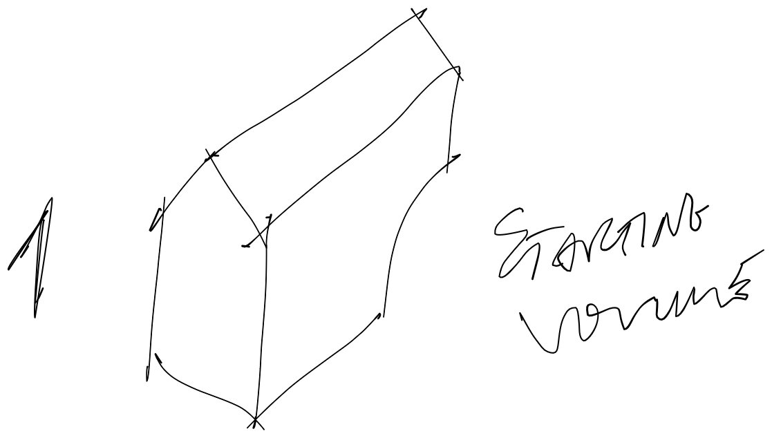
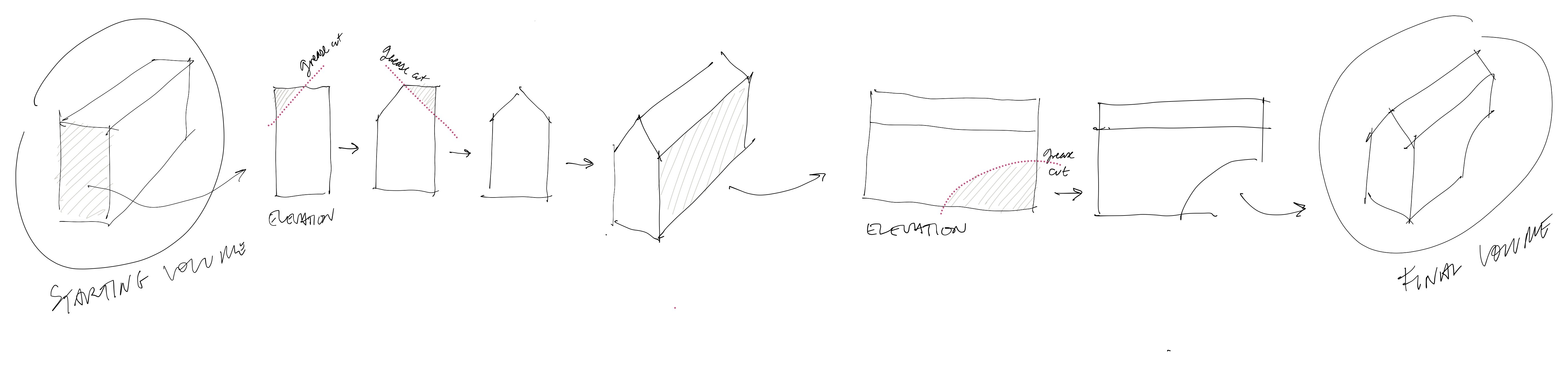
    1 - START WITH A VOLUME

    Imagine that you have a starting volume and not a plan view of a floor volume. You could have modeled in any way you wanted and I would also suggest a method to mass your volume with grease pencil, but let's leave that for the end.

    You would now use Grease pencil on it. So you have an initial massing study. Something like this:

    2 - SPLIT IT INTO FLOORS

    Now we just look at it sideways and start splitting it in floors with the grease pencil, like this:

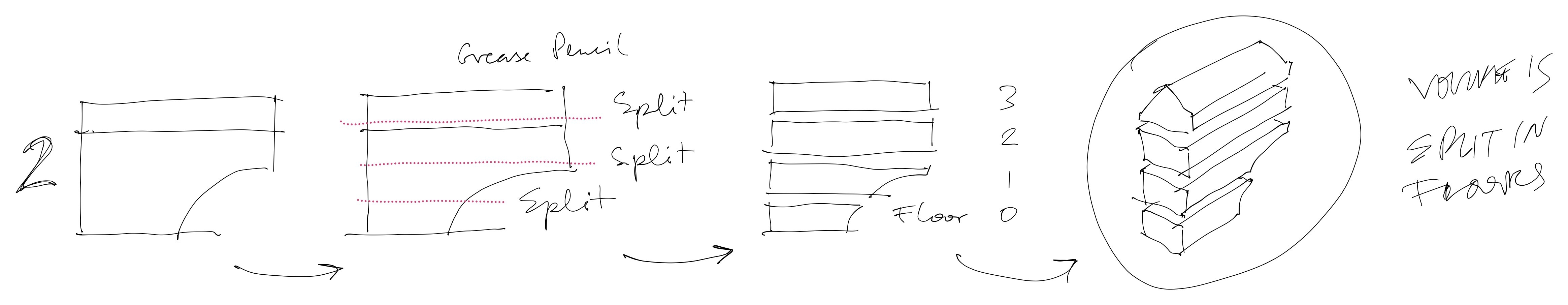
    Like you did but for a building mass.

    3 - PICK A FLOOR AND SPLIT IT INTO SPACES

    Then, it would be a matter of defining which floor you would want to work with, isolating it and apply the same method to split it into spaces.

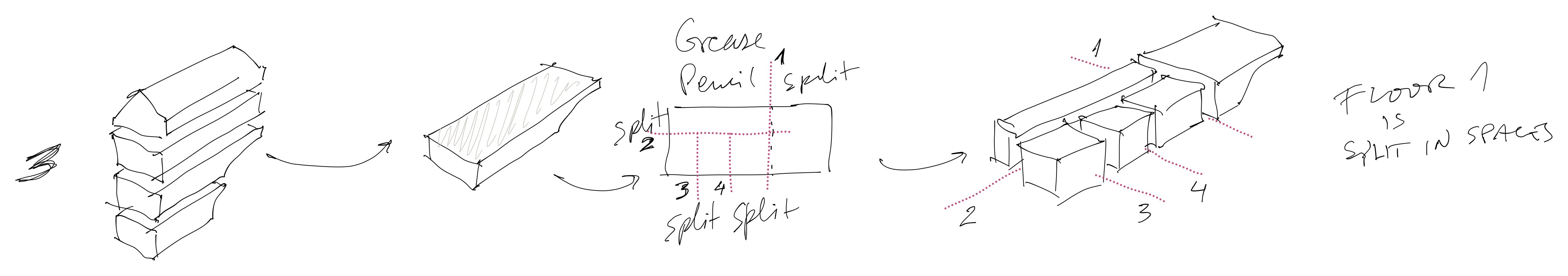
    We would thus split the floor into spaces to create a base floor plan.

    4 - COMMON FLOOR ELEMENTS

    If you'd want to replicate this floor plan to all floors, you could.

    If you'd just want to pick some of the elements and carry them to other floors, you also should be able to.

    That would allow us to either define typical floors, or define elements in the building that should be carried over to other floors. When drawing those extra floors we would have a base to stick to, when sketching their spaces.

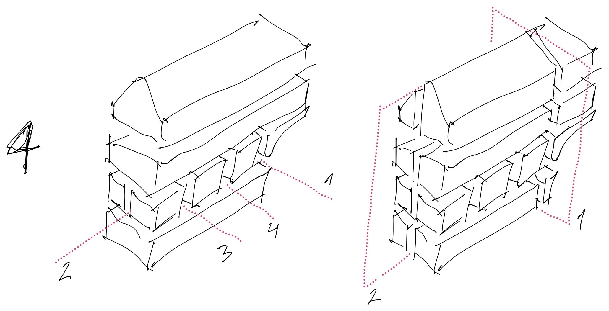
    After defining common elements we could then be able to isolate each floor at a turn, have the replicated elements already in place, and be able to design all other spaces based on them.

    5 - DEFINING FAƇADE, SLAB AND WALL THICKNESS

    I honestly wouldn't bother with that. You're using Sverchok and Topologic is being adapted to it as we speak. It will probably be a matter of using your tool to sketch and having topologic doing the rest.

    6 - GETTING BACK AT THE START

    What if Grease Pencil could be used to sculpt the initial shape like this:

    A perfect world :)

  1. Page 1
  2. 2
  3. 3

Login or Register to reply.