Hi all,
this is a "very simple workflow to deal with BlenderBim" thah I used to get an IFC project. I attach some images triying to show where find the tools used and the text is mainly "google translated" so maybe there is some mistakes and is not enoug clair, but think can help to deal with BlenderBim in a "simple way".
1.- Context.
In the government agencies with which I sometimes work, the use of formats associated with the BIM environment and the delivery of projects must necessarily be formalized, in addition to the usual formats (dwg, word files, etc.), in * format. .ifc with different requirements. These, fundamentally, consist of adding to the objects or sets of determined properties and associating them with the corresponding value.
The type of projects I work with is not only the "traditionally associated with BIM", this is architecture projects located in a "reduced" area (such as a roundabout project) but linear works projects associated with highways with certain length (6000 meters or in some case 14000 m).
Traditional software tools (at least the ones I have) did not offer an adequate solution for these requirements (something that fortunately is changing but also at a high price) so I decided to try the free alternatives that at that time (approximately one year ago) I was able to find, mainly freecad and blender (with blenderBIM and blenderGis addons).
2.- Work flow.
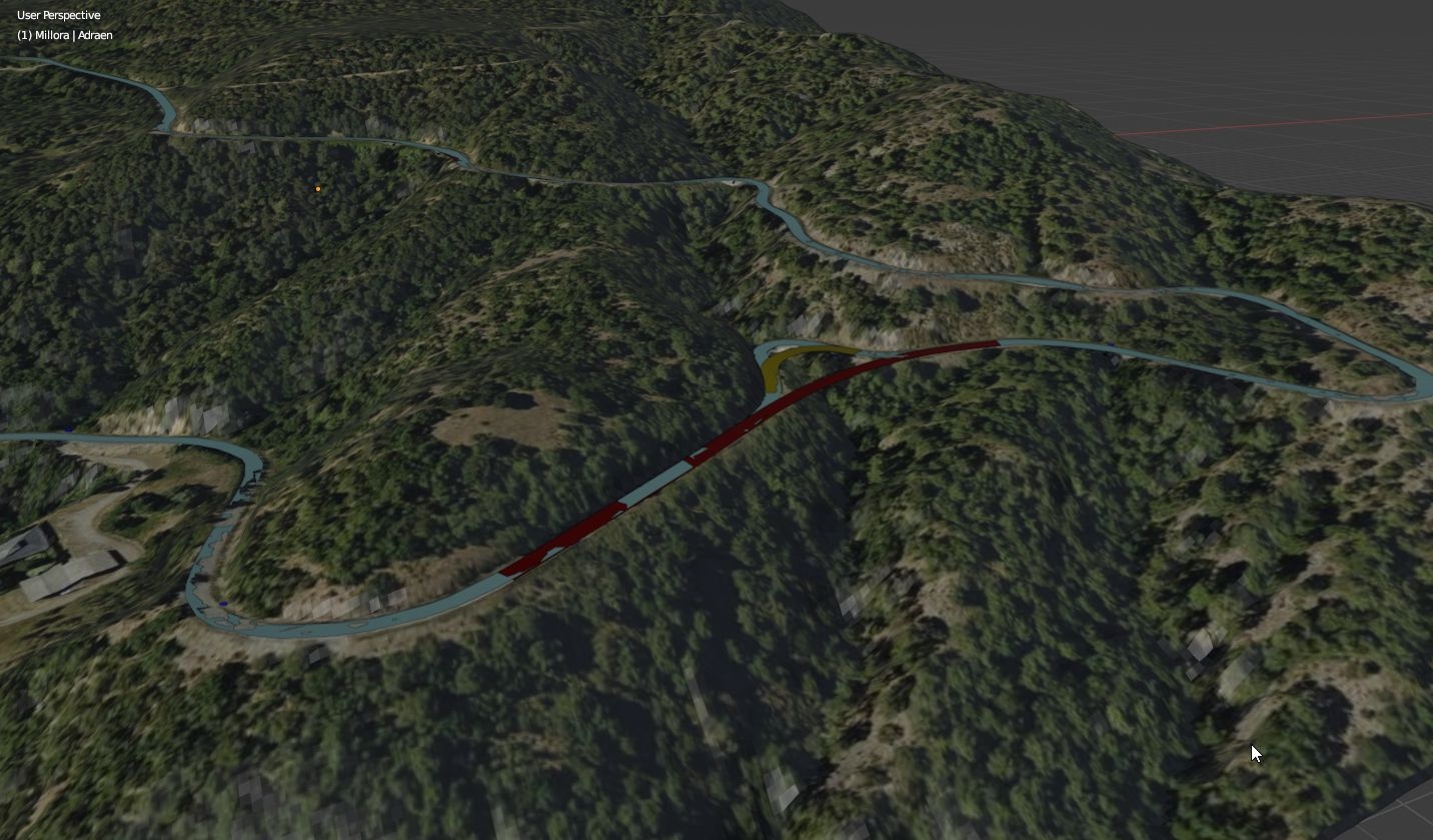
These free software programs did not always have the tools I needed to create the project (for example, the layout of a road) so I decided to previously create the model in cad format with the tool I usually used and then incorporate it into blender through import ( with a previous conversion from .dwg to .cae or wavefront). In this way I manage to introduce the objects in blender to create the IFC project.
The direct import of the objects initially did not work because importing objects in their real coordinates caused problems in Blender (Y coordinates of the order of 4,550,000) so I decided to georeference the scene and set a new point of origin close to the objects so that the value of its coordinates was not very high. Thus, by moving the objects in cad near the origin, I manage to avoid the problems in Blender and the import occurs without problems, obtaining a model displaced in coordinates with respect to the original.
You have to pay attention to the units in the scene after each import because depending on what software the * .dae or wavefront format is generated with, they are modified in Blender and must be restored. Also note that in the import I use the option "import units" activated
Objects in another format can also be imported and placed in their correct position with the "translate", "rotate" and scale "tools in blender.
3.- Creation of the IFC model
The truth is that I hardly know the use of Blender and I only use some basic commands to obtain the model according to the requirements I need. I also have no knowledge of IFC beyond the "curious user" level.
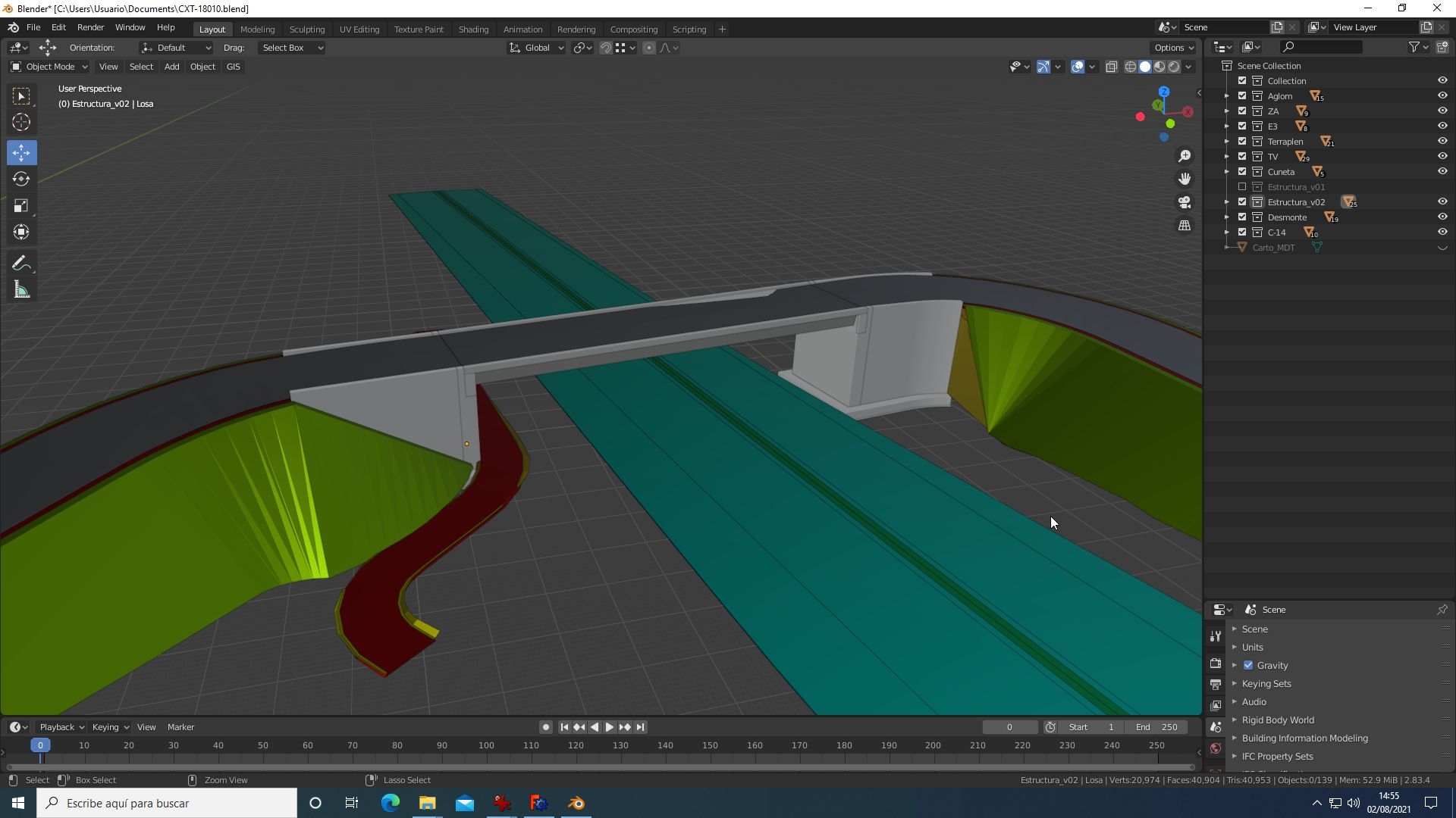
I do the importing of objects before creating the ifc structure of the project (although it can be done later) and in Blender I do some basic edits to simplify what is obtained. For example, the plotting program that I use creates a mesh for each carriageway on the road, with coincident but separate nodes that I merge (in "edit mode") I also join some separate objects on import that are part of the same layer (for example imported agglomerate layer is formed by the separate meshes corresponding to the top, bottom surface, left and right one to have a single layer such object models).
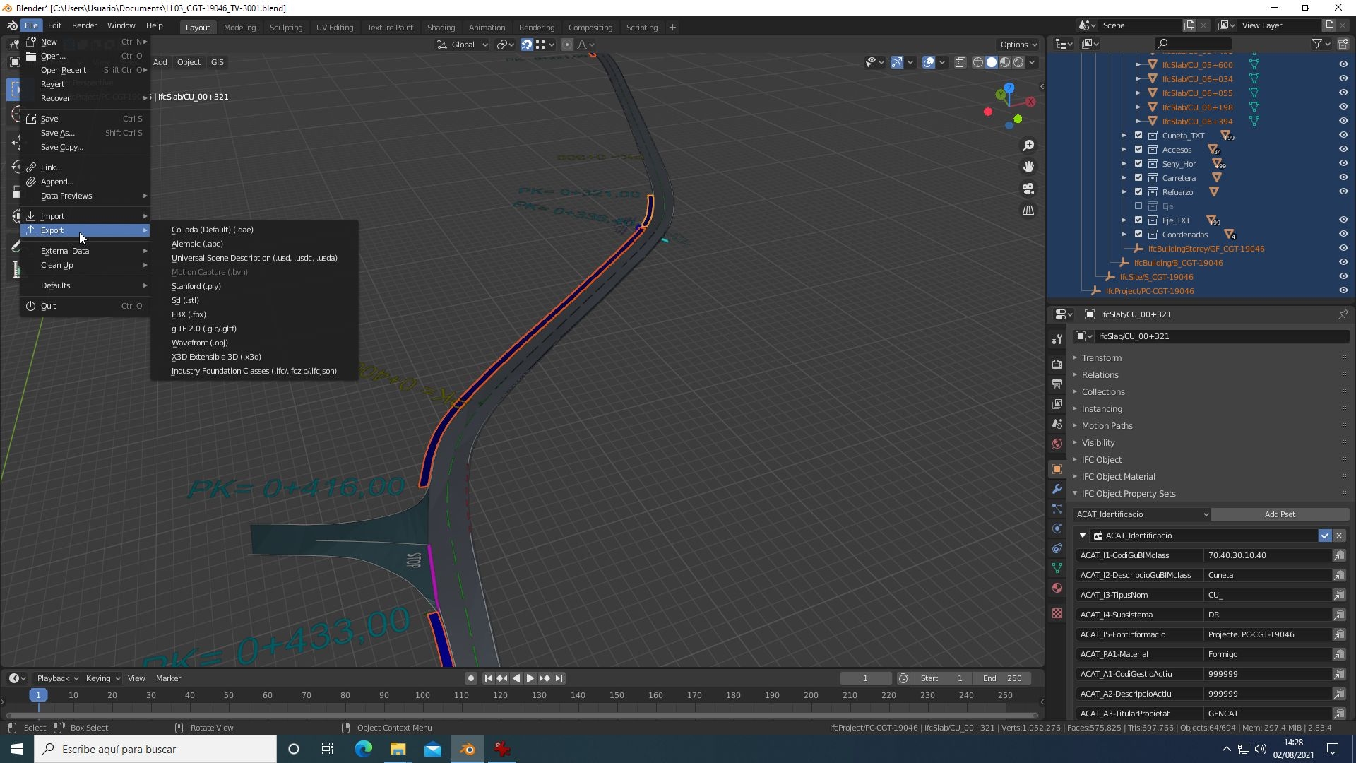
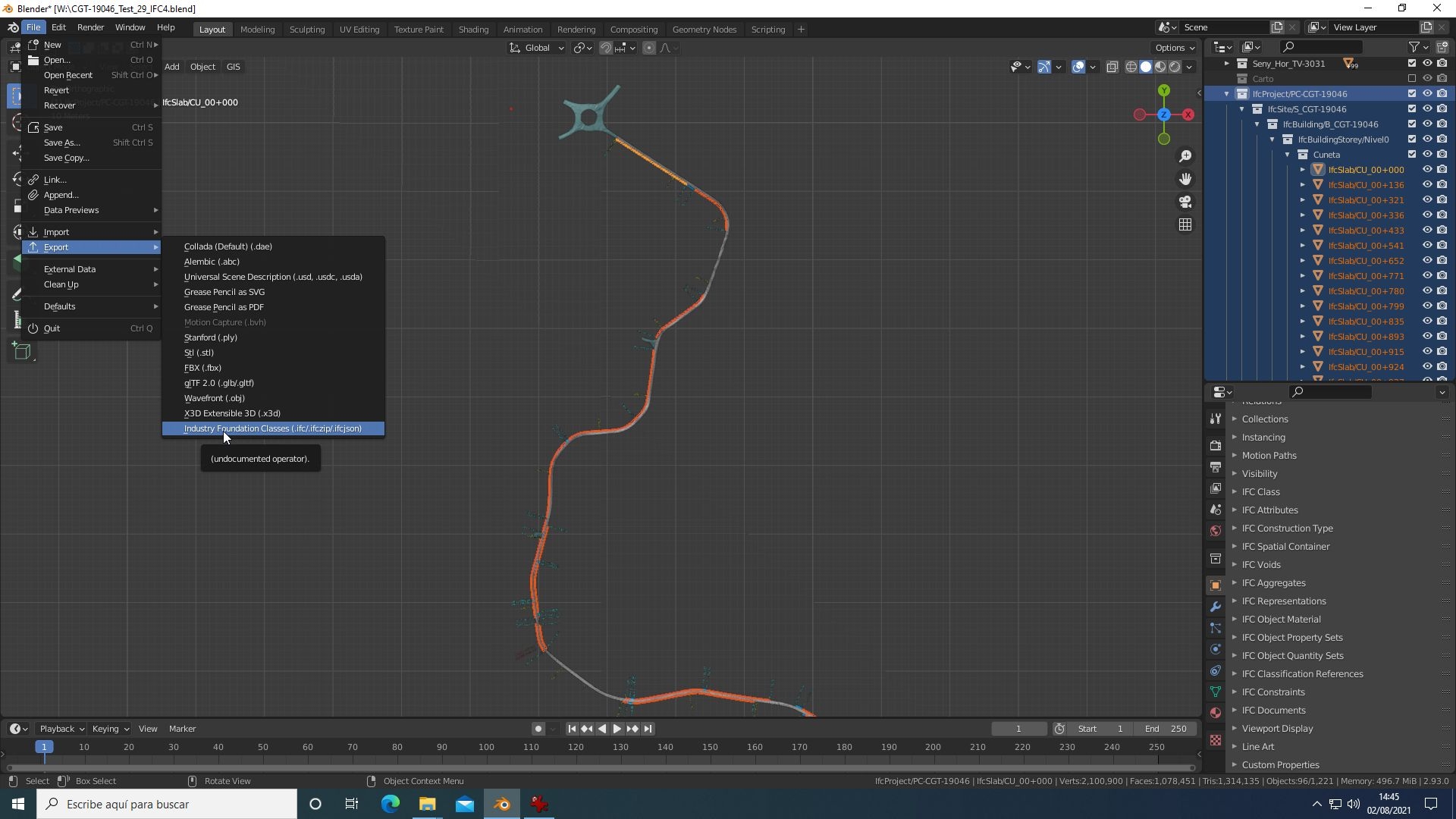
3.1.- Creation of the ifc project
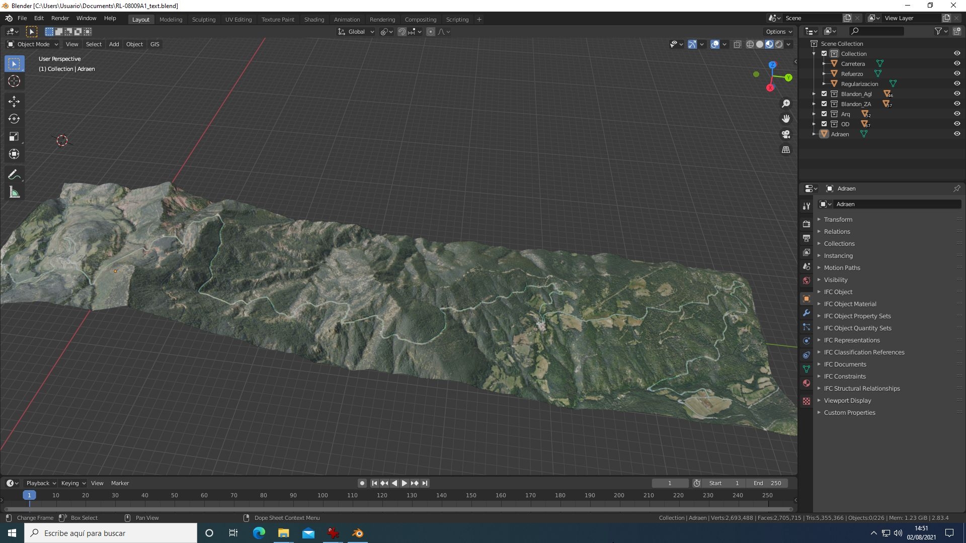
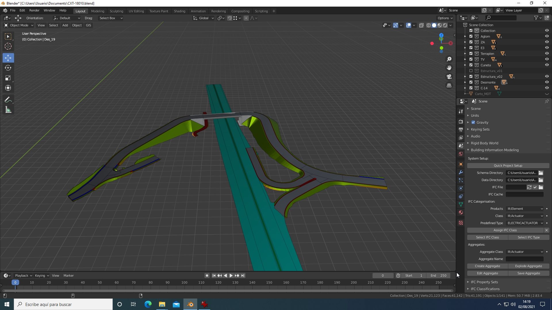
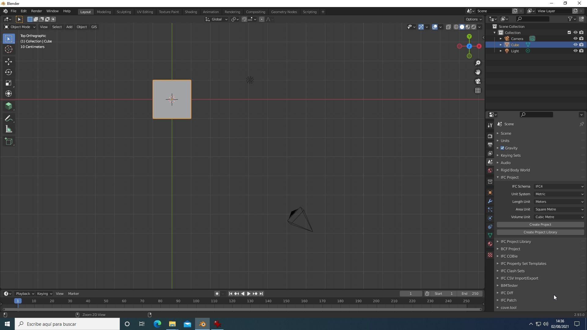
To create the * ifc project, go to the blender "scene properties" icon, fill in some values in the ifcProject panel that appears and press the "create project" button. This makes the basic structure of the ifc project appear in the "outliner" panel (ifcProject element, ifcSite, ifcBuilding, etc.) that will be containers for the objects.
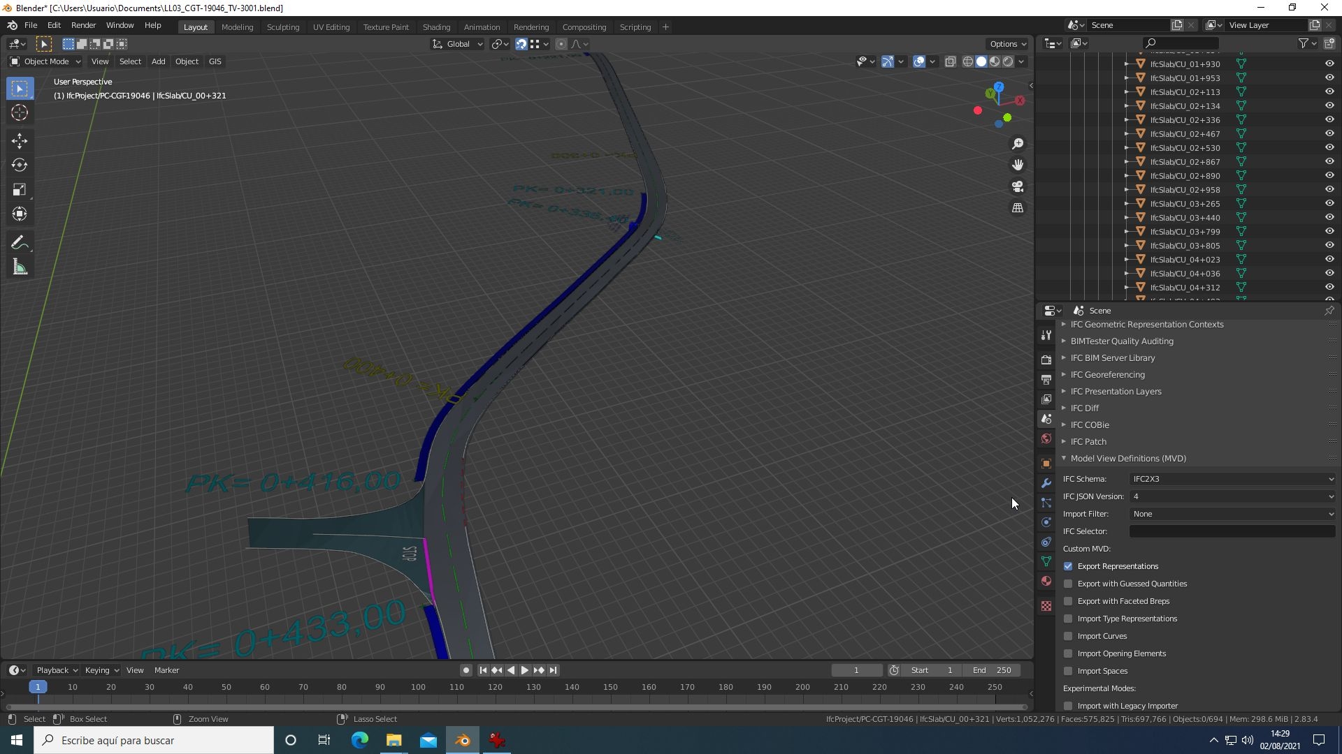
Depending on the version of blenderbim addon used, the information for creating the project may appear in different panels. In version 201207 you must search for "Building Information Modeling" and in 210729 you must search for "IFC Project" and some additional information is shown in other panels (for example the choice of version IFC2x3 or IFC4, etc.) so if you do not you know exactly where it is, you have to browse the different sites until you find it. In the latest versions, this information appears directly in the ifcProject panel.
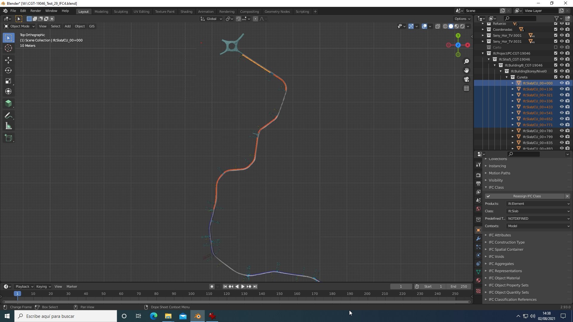
3.2.- Assignment of ifc classes to objects
With the project structure created, each object that wants to be added to the project must be assigned its associated ifc class. Depending on the version of blenderbim addon that you use, this is done from one or another blender tab. I have used the versions 201207 with blender 2.83 and 210729 with blender 2.93 and they are the ones I explain.
- for 201207 you must go to the "scene properties" panel, select the outliner objects and assign the corresponding class
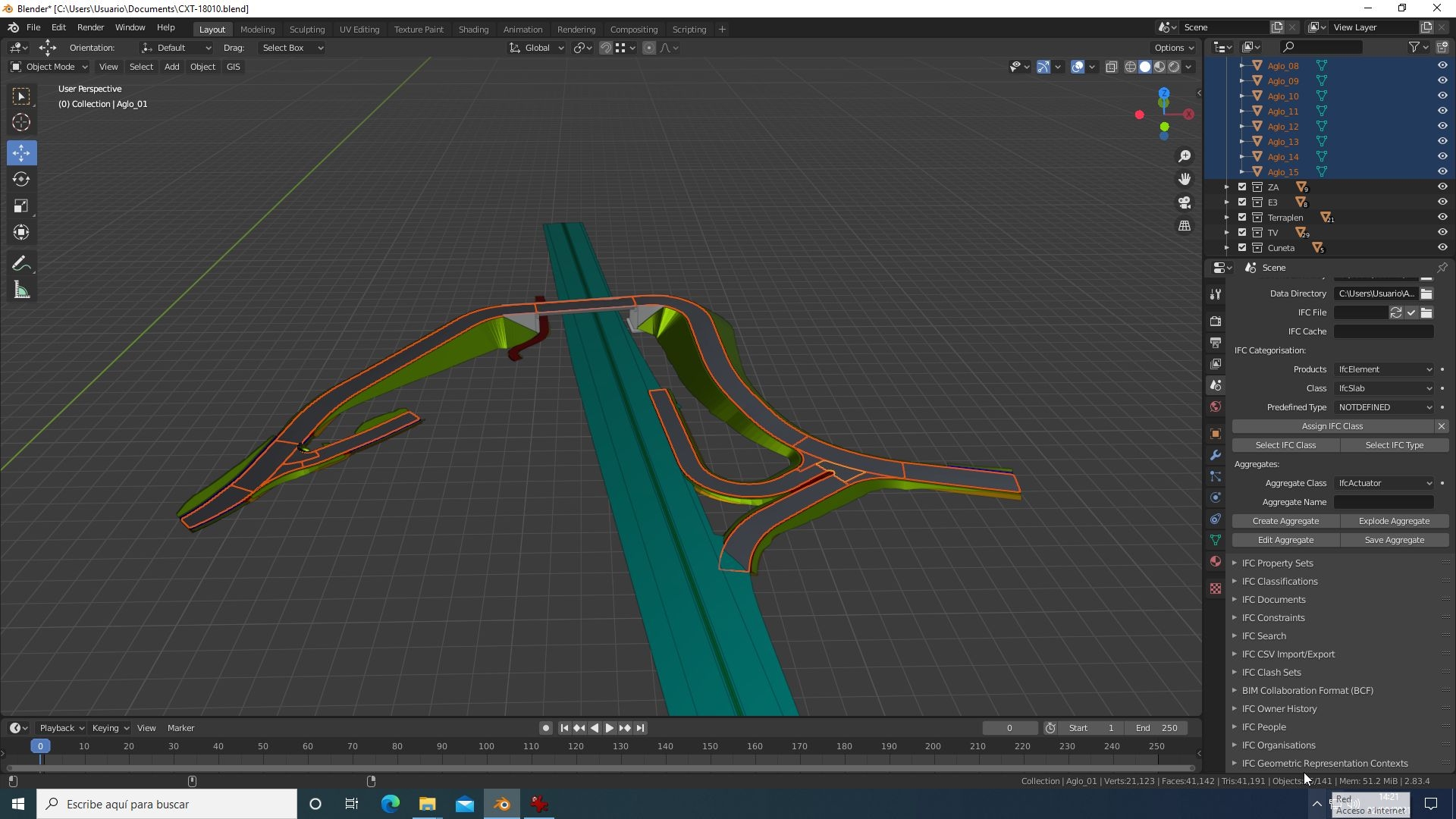
- for 210729 you must go to the "object properties" panel, select the outliner objects and assign the corresponding class.
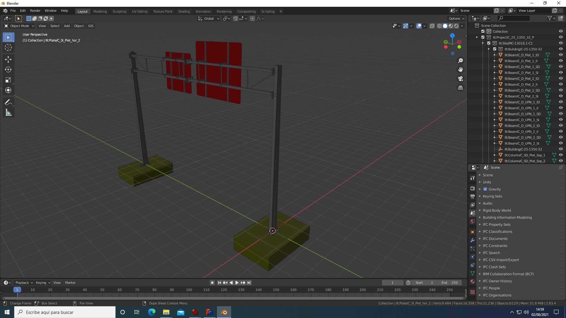
After that, select object in the outliner, drag and drop-them inside the IfcBuildingStorey object. This add selected objects to the ifc project.
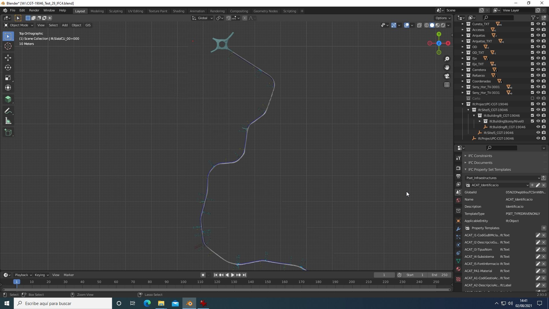
3.3.- Creation of a set of user properties ("user pset").
Each object included in the project can be assigned one (or more) sets of user properties "user pset". To do this, you must previously define these sets of properties in a * .ifc file that is stored in "C: \ Users \ User \ AppData \ Roaming \ Blender Foundation \ Blender \ 2.83 \ scripts \ addons \ blenderbim \ bim \ data \ pset" (or add them to an existing one) using the tools that appear in "IFC Property Sets" for version 201207 or "IFC Property Set Templates" for version 210729 of the "scene properties" panel
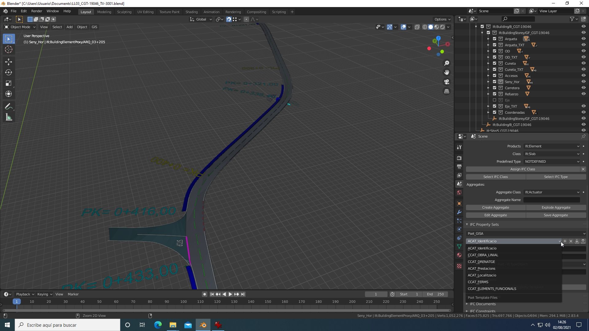
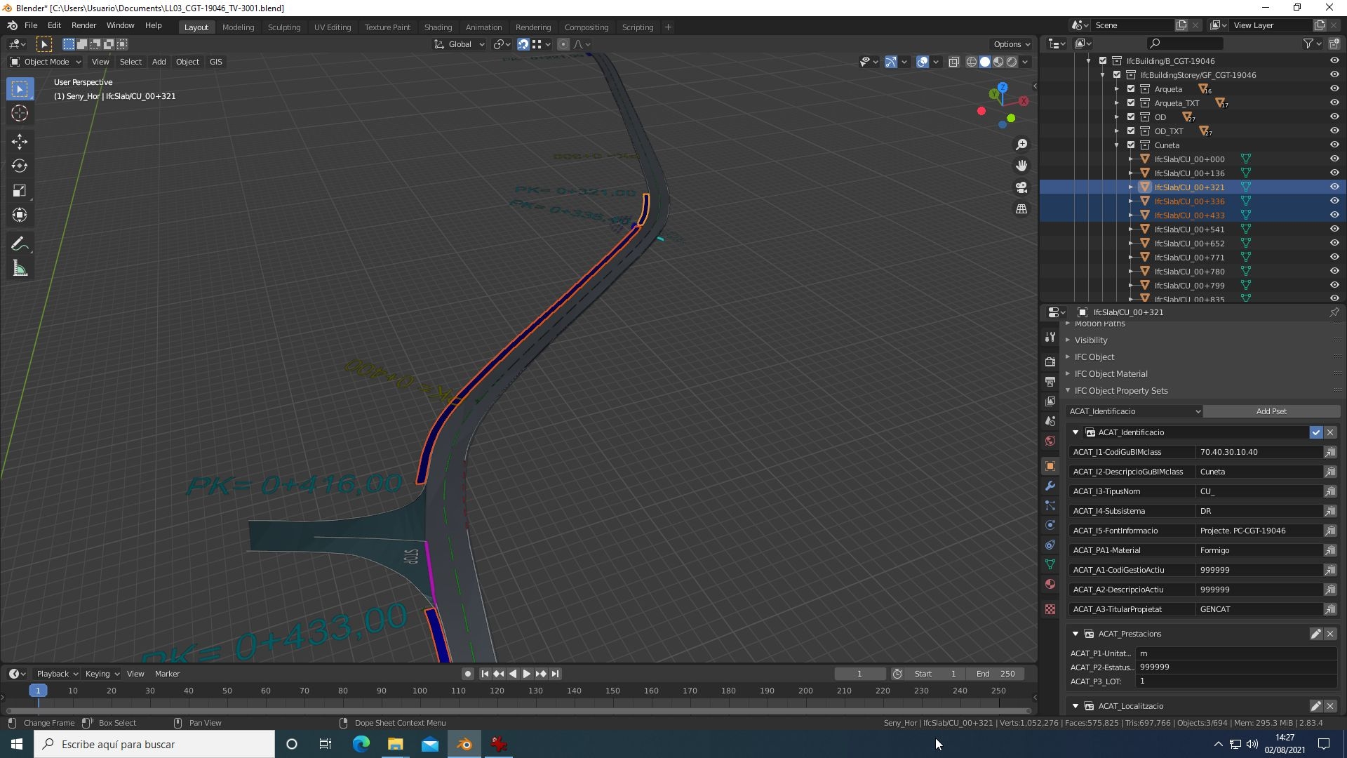
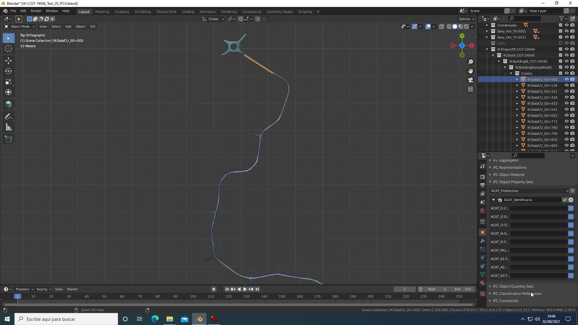
3.4.- Assignment of a set of properties and properties to objects
After property sets are defined, they must be assigned to objects. This is done from the "object properties" panel using "IFC Object Property Sets".
The objects are selected, the desired property set is chosen from the drop-down control, and they are added. In version 201207 this assigns the property set to all selected objects but in 210729 only to the first selected object.
By clicking on the set of properties assigned, it is displayed and shows the included properties that can be edited. In version 201207, the entered (or modified) value can be transmitted to the rest of the selected objects by means of the "paste" icon that is shown in the edit field. In version 210729 the edition only affects the selected object value and the data entered cannot be transmitted easily; You must assign the set of properties individually to each object, activate said set as editable in each object and then copy the value by pressing the right button of the mouse in the editable field and use "copy to selection".
This system is not viable if the number of objects is high and the implementation of the previous version is preferable.