Y
by yorik on 26 May 2020
#
If you look at the others agreements there (press the "next" button), there are all kinds of strange things (roofs MUST be assemblies, "geo coords should be exported if they are available, otherwise they shouldn't be exported"), honestly I think it will give us a lot of headache if we begin to need to check manually these kind of non-standard standards... Specially when we have a schema, that clearly says what can and what cant, that is usable by a machine, and that is implemented by IfcOpenShell so it automatically doesn't allow things not allowed by the schema. My opinion is more that these things are meant for future versions of IFC, and we should follow them when they are part of the schema.
We could make "empty" buildings have a default placement in FreeCAD's IFC export, it's not a big deal, but it seems to me we would unnecessarily be adding superfluous information to the file...
M
by Moult on 28 May 2020
#
I agree that the implementer agreements need some rethinking ... there was a recent decision to merge the agreements into the spec, and that might be the prompt to reconsider some of these agreements.
In any case, FreeCAD's behaviour is not illegal, so I'm now supporting it :) https://github.com/IfcOpenShell/IfcOpenShell/commit/bdf17e5c122720c64f048af17c3cbff1ea4ec582
Y
by yorik on 29 May 2020, edited 29 May 2020
#
Good way to solve things @Moult ... IMHO it's cool that apps are tolerant to IFC "dialects"...
I added FreeCAD files for @Moult 's second test (mapped items) which I'm happy to say FreeCAD passed easily ;) and added a third test (extrusions of circles and rectangles), which of course BlenderBIM will probably fail, as these entities don't exist in Blender, but it seemed to me an interesting topic to look at anyway, since it is something we discussed earlier already... So maybe this is a good opportunity to try to tackle it in some way...
T
by theoryshaw on 30 May 2020
#
@yorik, in the latest commit, I'm proposing to break out the extrusion tests into more grandular tests. That is...
-
1 test for extrusions with rectangles
-
1 test for extrusions with circles
-
1 test with extrusions with arcs
I feel having a (1) test with both rectangles and circles added too many variables by which to test against. Have just (1) profile typology in one (1) test makes it easy to report what in that test worked, or not.
T
by theoryshaw on 30 May 2020
#
As you can see, I'm proposing to create a new OSarch thread for each test as well.
M
by Moult on 30 May 2020
#
This is fantastic work @theoryshaw ! I do need to make some time to improve the native representation support in the BlenderBIM Add-on. By the way, perhaps this is better on the OSArch Wiki? More people can edit, and I expect this to grow to include things like advanced BREPs, IfcAlignment, ParameterisedProfileDef ... I can say for sure that the NSW government body was very interested in results like these ...
T
by theoryshaw on 31 May 2020, edited 31 May 2020
#
Thanks Dion. I personally like keeping this documentation on git, as it allows others to fork, and it keeps the documentation very close to the associated files. I could see, as this evolves, there could be a tighter connection, or even automation between the files and the documentation.
How about creating a OSArch group on Gitlab and forking this FreeMVD repo? I'd be happy to push experiments to that instead. @yorik what's your thoughts?
Y
by yorik on 31 May 2020
#
Agree! Osarch will need a git repo sooner or later ;)
T
by theoryshaw on 31 May 2020
#
very cool. Dion, I pulled the repo over to gitlab, if you want to fork it to an OSarch group repo.
https://gitlab.com/openingdesign/FreeMVD_WorkFlow
Cheers!
M
by Moult on 31 May 2020
#
@theoryshaw fully agree with your logic! I haven't got an OSArch group repo yet - would you like to start one? You can lead it! :)
T
by theoryshaw on 1 Jun 2020
#
+1 votes
Cool.. done! https://gitlab.com/osarch/FreeMVD_WorkFlow
Gave you and @yorik owner privileges for the group, feel free to add whomever.
M
by Moult on 7 Jun 2020
#
+1 votes
@yorik said:
... a third test (extrusions of circles and rectangles), which of course BlenderBIM will probably fail, as these entities don't exist in Blender ...
Coming soon :) https://github.com/IfcOpenShell/IfcOpenShell/commit/0237f12cebc5b1d324cb26b454e16414bc4d77e8
T
by theoryshaw on 7 Jun 2020, edited 7 Jun 2020
#
Very cool...look forward to testing.
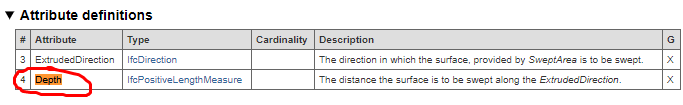
Upon import, is the depth attribute accessiable in blender via a modifer or similar?
M
by Moult on 7 Jun 2020
#
@theoryshaw the depth will be implicitly shown in the object itself. Internally it will be stored - maybe it should be exposed hmm :)
Blender's extrusion modifiers (solidify, or curve extrude) only extrude normal to the plane. This is not sufficient to support the custom extruded direction feature of IFC. Also, an object may include both extrusions and BREPs simultaneously - Blender will be able to handle them, but it means I cannot use modifiers.
Y
by yorik on 8 Jun 2020
#
Amazing development @Moult !
In any case this is a slippery area, there are many IFC cases that don't translate 1:1 to neither Blender or FreeCAD (or Revit for that matter :D ). But circles are a convenient thing to support since they appear a lot everywhere in buildings and you can usually reduce your filesize by a big factor. Maybe just a kind of "export as circle" switch somewhere would be sufficient? Then you could easily deduce the radius I think, from the center point and one of the vertices
T
by theoryshaw on 8 Jun 2020, edited 8 Jun 2020
#
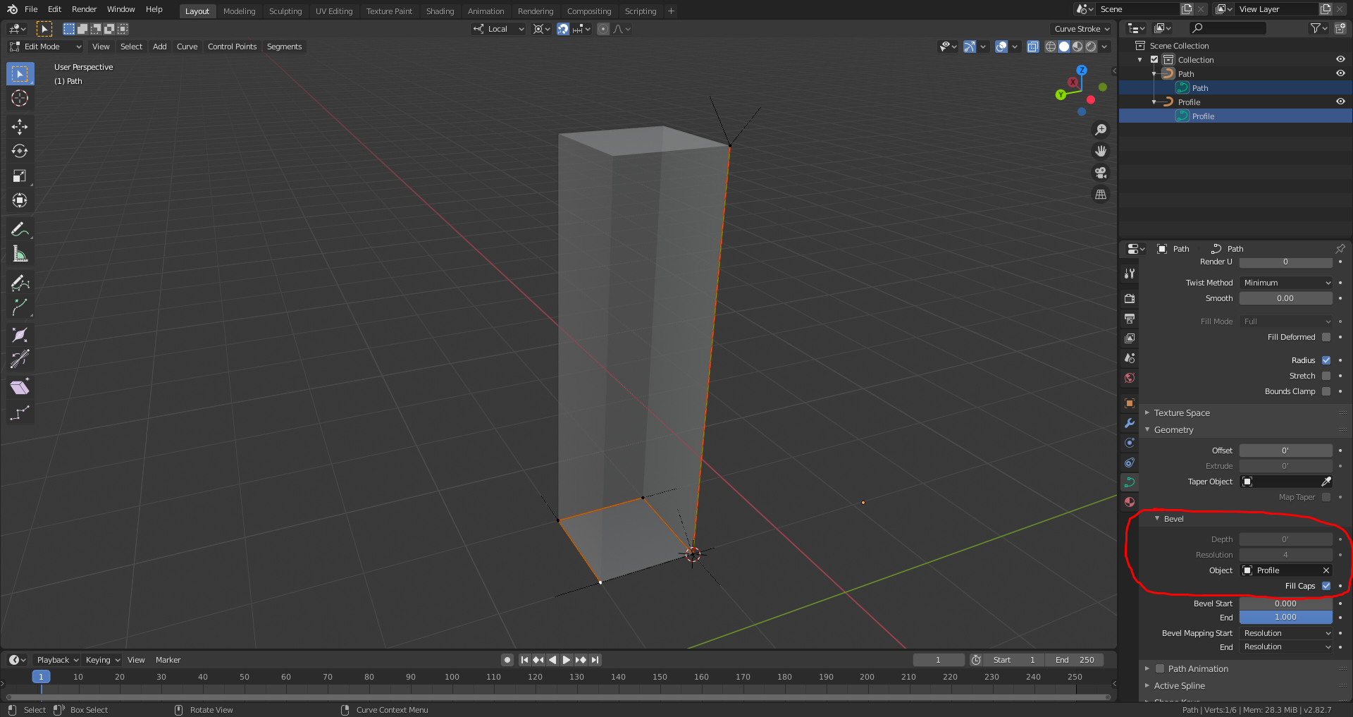
@Moult is the profile exposed too in blender? If not, I feel it should. Otherwise I feel it would be cumbersome to modifiy the profile in blender, as you would have to 'explode' and re-extrude.
Retaining the profile, would also play into accommodating 'mapped profiles' in the future--could tap into libraries like these: https://github.com/OpeningDesign/BIM_Profiles
--
Also, I would say a vast majority of extrusions in AEC are normal to the direction of the profile. Is this one thing we could be strict on? Would this help to develop an implementation where the profile and extrusion distance were exposed in blender?
T
by theoryshaw on 8 Jun 2020
#
In any case this is a slippery area, there are many IFC cases that don't translate 1:1 to neither Blender or FreeCAD (or Revit for that matter :D ). But circles are a convenient thing to support since they appear a lot everywhere in buildings and you can usually reduce your filesize by a big factor. Maybe just a kind of "export as circle" switch somewhere would be sufficient? Then you could easily deduce the radius I think, from the center point and one of the vertices
Would extruding a 'Nurb Circle' verses a 'Mesh Circle' be a better approach to emulate a true circle?
T
by theoryshaw on 8 Jun 2020
#
Would translating IfcExtrudedAreaSolid into a 'bevel extrusion' via blender, be a better approach?
T
by theoryshaw on 8 Jun 2020
#
I'm a blender noobie of course, but seems like 'mapped profiles' could be done like this.
M
by Moult on 8 Jun 2020, edited 13 Jun 2020
#
@theoryshaw I've considered those options - there are a few downsides to a Blender curves approach (applies both to arbitrary profiles and circles - note that Bezier-based circles are not true circles, they are approximations ... not that the error factor matters though!)
-
No support for custom extrusion direction
-
Only support for a single curve, it is possible for an IFC object to have multiple extruded solids in a single object
R
by ReD_CoDE on 12 Jun 2020
#
@Moult this is my friend's view:
If you consider a non-rational B-spline (NUBS), then you are correct. However, rational B-splines (NURBS) are designed to represent geometries like a circle, sphere, cone, etc.
M
by Moult on 13 Jun 2020
#
@ReD_CoDE your friend is correct. My statement should've been about Blender's bezier curves. I have modified my post.
M
by Moult on 18 Jun 2020
#
+3 votes
https://github.com/IfcOpenShell/IfcOpenShell/commit/d3f07c4ac48e85e714073b9c213a90a5797793f4
@theoryshaw The BlenderBIM Add-on can now round-trip IfcArbitraryClosedProfileDef and IfcRectangleProfileDef :) Will be in next release! Full log here.
T
by theoryshaw on 18 Jun 2020
#
+1 votes
Nice!... look forward to testing.