OSArch Community

Integration of Code_Aster in an IFC-driven workflow for structural analysis

  1. J

    @Moult I want to improve some of the work done in ifc2ca and set some more stable base on some aspects, especially the geometry and orientation of structural members and structural connections. As of now, I have not really considered at all object placements and stuff, treating all coordinates as global and orientations as global or default as well, but I feel I have to cope with this well, above all for defining then correctly the implementation in Code_Aster. I will be taking a more offensive approach (I am not good in asking questions but I have to improve) providing my interpretation here and asking if that is correct, hopefully this can be a more efficient way to go forward.

    Of course anybody that will be able to verify my interpretation or guide me in the correct direction is welcomed to help.

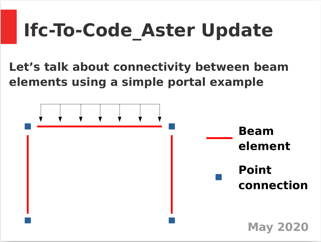
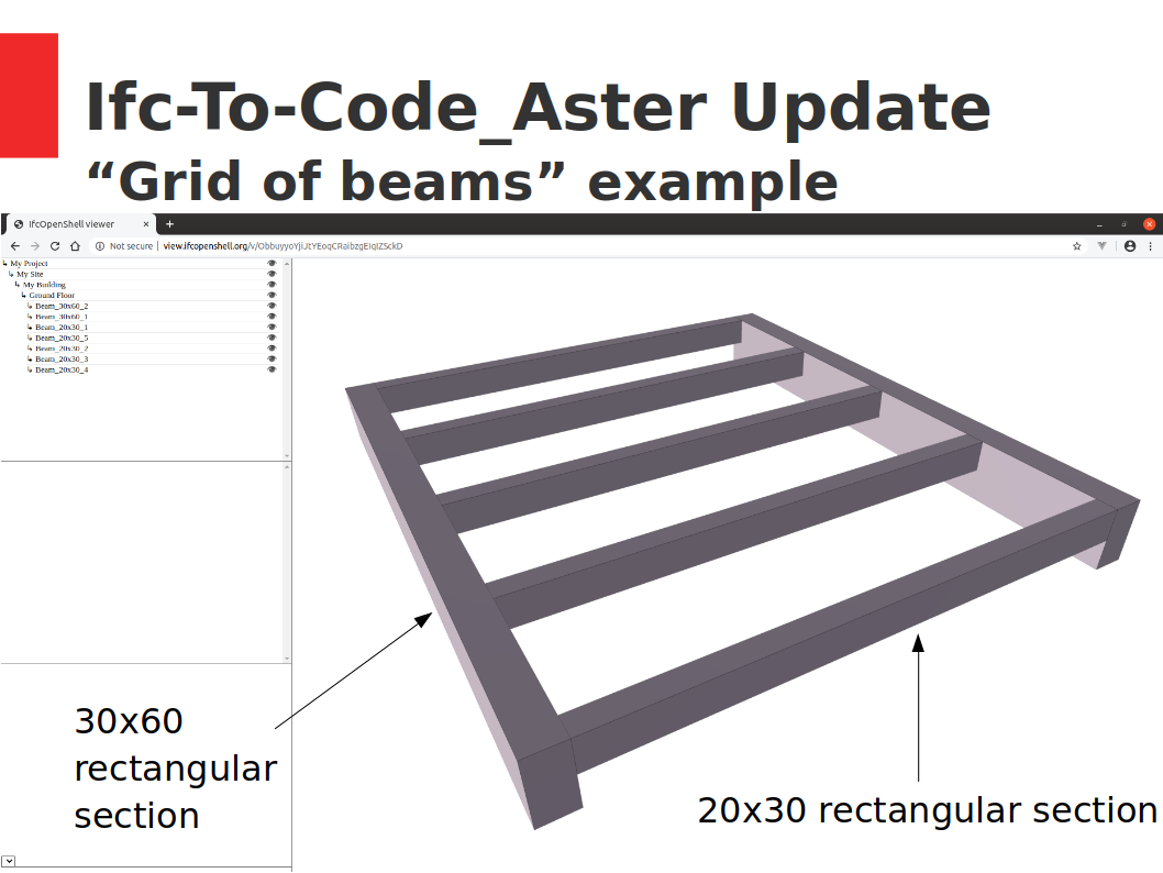
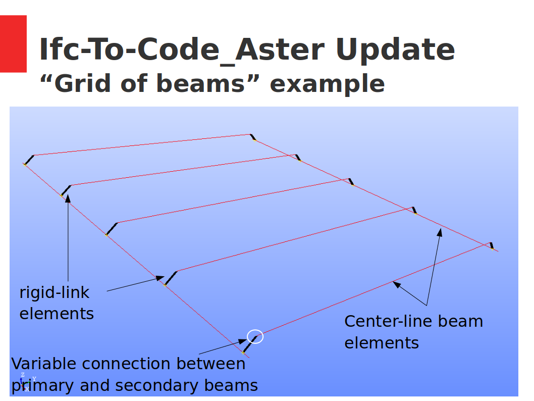
    So, let's start with the geometry coordinates of the objects, members and connections.

    My understanding is that I have to consider two transformations (where each transformation can have translation and rotation in 3D) to get the global coordinates from the coordinates I read from the representations:

    The SharedPlacement property of IfcStructuralAnalysisModel (sth similar to WorldCoordinateSystem of IfcGeometricRepresentationContext)

    The ObjectPlacement property of IfcStructuralItem or IfcStructuralConnection

    Would that be correct in your opinion? Or there can be other transformations possibly to consider?

    For the SharedPlacement the documentation states "Per informal proposition, this attribute is not optional as soon as at least one IfcStructuralItem is grouped into the instance of IfcStructuralAnalysisModel."

    My understanding is that it is a mandatory property. What's your take? If not provided should I relate to the WorldCoordinateSystem or just ignore it overall?

  2. J

    Thinking more on this I guess the placement of the model itself is not important for the structural analysis. And if all members/connections have the same object placement I will not have to account for any of that (?)

  3. M

    Correct, the placement of model is not important for structural analysis so long as all items are relative to one another. This makes life easy :)

    I would ignore the WorldCoordinateSystem for now, since it may only apply if you need to convert local coordinates to a global CRS. This is definitely never required in a structural analysis workflow.

    From my reading of the documentation, it seems like the object placement of all structural items must be the same, and then once you place it in an analysis model, that must also have a SharedPlacement property that has also, the same object placement. Therefore I do not interpret the SharedPlacement as an additional transformation to be applied - it seems like superfluous metadata.

    If one or more structural item is grouped into an Analysis Model, the attribute SharedPlacement shall be provided with a value.

    The object placement of all structural items which are grouped into the same instance of Analysis Model shall refer to the same instance of as .SharedPlacement.

    So I guess if I had to parse it, I'd just read each structural item's object placement and call it a day without applying any more transformations.

    I hope I've understood it right.

  4. J

    Ok, I think it makes sense, I will be considering only one possible transformation related to the object placement, thanks

  5. J

    Finally, some updates on the Ifc-To-Code_Aster project. I prepared a brief deck, attached here as images, to show the current state of development through a simple portal example. Glad to say that internal releases of beam elements with respect to any arbitrary orientation is now implemented and it looks great!

    Point supports can be also defined with any orientation although this case is not covered in these examples.

    Next targets down the road? Implement elastic internal connections and elastic supports for beam elements and point connections, respectively.

  6. Y

    That's awesome! In FreeCAD, structural elements like beams and columns already contain a linear representation. So far, this isn't exported to IFC, though. I'd be glad to work through that at some point, so we can export files that are ready to process in CodeAster..

    If someone happens to have a very simple IFC file with, say a portal like the image above, I'd be really interested in having a look at it

  7. J

    @yorik that would be fantastic! I am available to provide any support necessary towards this direction.

    In the analysis-models repository of IfcOpenShell there are a few models you can see.

    This example (portal_01) is actually the ONLY one provided by buildingSmart (original link here).

    cantilever_01 was created by @Moult in BlenderBIM while beam_01, building_01 and building_02 have been extracted from ETABS, a commercial structural software. The last two that contain also walls and slabs have various problems as there are no connections between surface elements. I would suggest you to see portal_01 but also cantilever_01, which I think is created more to the state-of-the-art, especially regarding representation contexts and material properties.

  8. Y

    Great! @Moult 's example is super interesting because it combines both "physical" model and analysis representation. I'll try to do that as well in FreeCAD. To resume what I found out:

    • There are two (or more) IfcGeometricRepresentationContext: one for normal geometry (body) and one for wireframe structural analysis. But that is apparently just for model cleanliness, to separate all the representations of one type from another.

    • There is an IfcStructuralAnalysisModel entity which relates to the IfcProject (weird way to define that this is an analytic model If you ask me... what about all the fuss with MVDs)

    • You cannot apparently have an IfcBeam with structural analysis properties. So if you want to have structural analysis, you MUST use IfcStructuralItem-derived object (IfcStructuralCurveMember, IfcStructuralPointConnection, etc)

    • Representations of structural items are made of IfcTopologyRepresentation, which are made of edges (for members) or vertices (for point connections).

    • The member product has one representation (the edge), and connects to point connections via IfcRelConnectStructuralMember

    • The member can have another representation (a 3-dimensinal body). I don't see however how an application can distinguish between the different representations, which one is to be used for structural analysis, other than figuring out by the name ("body" or "edge", for ex),or by the representation context it is associated with (but there too there only differ by name, so it is pretty weak

    Anything I missed?

  9. J

    I think you got it pretty right. Here are some minor comments and I hope Dion can chip in later with more comments

    There are two (or more) IfcGeometricRepresentationContext

    To be more exact they are SubContexts, although in the other files other than cantilever_01 SubContexts are not used.

    Furthermore, I think the context for structural elements is 'Reference' which is used in both cantilever_01 and portal_01, although the latter does not define it in the beginning like in the former.

  10. M

    @yorik ask and you shall receive :) https://github.com/IfcOpenShell/analysis-models

    By the way, the structural entity is completely independent from from linear representation in the IfcBeam / IfcColumn etc. In fact, you can have a structural beam in IFC without even having an IfcBeam ... weird, I know! You can still derive one from the other, but just a heads up :)

  11. Y

    Okay we now have something up and running in FreeCAD!

    Commit: https://github.com/FreeCAD/FreeCAD/commit/6271887cc656d8571000de2f4e06df2be8d84105

    Basically, with this commit, under Edit->Preferences->Import/Export->IFC export, we can now set the export model to either standard (IfcProducts), analytic model, or hybrid (both). After that, it's just a matter of exporting a model to IFC normally.

    What happens:

    • All Arch Structure objects have their node lines exported as IfcStructuralMember

    • All objects that have no solids or faces (wireframes) are also exported as IfcStructuralMember (not sure if that is really useful, still testing)

    • All coincident points in the above objects are exported as IfcStructuralConnectionPoint

    • If hybrid mode, an IfcRelAssignsToProduct relates the IfcStructuralMember and the corresponding IfcProduct

    Here is a test file if anyone is interested in testing:

  12. J

    @yorik Wow! That is awesome! Will test soon and report back!

  13. B
  14. J

    @yorik I tested your example with ifc2ca and I have the following comments:

    1. In IFCSTRUCTURALCURVEMEMBER the last input is the Z axis of the element local axes. You have provided for all these elements:

    #7=IFCDIRECTION((0.,0.,1.)); but this direction should be specific for each curve member and certainly not parallel to the axis defined between the two points of the curve. From its definition

    The local coordinate system is established by the reference curve given by topology representation and by the attribute Axis. The local x axis is parallel with the tangent on the reference curve. The local z axis is located in the surface which is created by sweeping Axis along the reference curve and is directed according to Axis. The local y axis is directed such that x,y,z form a right-handed Cartesian coordinate system.

    Thus in this example the local axes for the vertical elements cannot be defined. As a rule of thumb I would say for horizontal curves it can be a vertical direction and for vertical curves (columns) can be along X or along Y global axis (preferable the latter in my opinion so that for a rectangle profile xDim and yDim are aligned with X and Y global axes

    1. In #24=IFCGEOMETRICREPRESENTATIONSUBCONTEXT('Analysis','Axis',*,*,*,*,#21,$,.GRAPH_VIEW.,$); I would expect to see 'Referenceinstead ofAnalysisandModelinstead ofAxis` but I am not 100% sure what you have provided is not ok. In any case I am modifying the ifc2ca script to read any subcontext that has an 'Edge' type as representation for a structural curve.

    2. I am also modifying the script to read the curve members even if there is no IFCRELASSOCIATESMATERIAL

    With all these considerations I can parse the file you provided and create the geometry and mesh.

  15. J

  16. J

    And a gif of the structural members + the mesh of the solids from ifcopenshell.geom.create_shape output

  17. Y

    Amazing!! Thanks a lot for testing @Jesusbill . I'll fix the Z axis already. For the name of the context, since this name is apparently arbitrary, I thought of using something more meaningful than "Reference", but it makes no difference to change...

    I'll also add support for slabs, @bernd suggested using IfcStructuralSurfaceMember

  18. M

    The Reference context name I think is a buildingSMART thing - they use it in their structural examples for how to store topology. I agree it seems a bit strange to me too :)

  19. J

    Update on the Ifc2CA project: All types of point connections between structural curve members (beams/columns/etc) have now been implemented. This includes:

    • internal releases AND/OR internal springs for each DOF;

    • RIGID links in series with internal springs;

    • external springs for point supports.

    An additional example has been added of a typical grid of primary and secondary beams, with a strict center-line modelling technique and rigid links to account for the correct length and position of the structural elements. Various cases for the beam-to-beam connections are investigated with rigid, pinned, or flexible, with user-defined stiffness, conditions.

  20. D

    Hi all. This is looking great and exciting. So I'm thinking about the best way to document it. I've created some things on the wiki

    https://wiki.osarch.org/index.php?title=Code_Aster

    https://wiki.osarch.org/index.php?title=Category:Code_Aster

    I think it would be great if some of the work in this thread could be done based on IFC from the FreeCAD model of the "Open Source House"

    https://wiki.osarch.org/index.php?title=AECO_Workflow_Examples

    I've got a not very secret plan to see if we can focus lots of processes on one project so we can document how we get closer to a full workflow. on a real project. There are parts of that project @bernd has worked on and have a geometry which I think is suitable. Maybe @yorik could use that file to add the necessary data. There is already some FEM done inside FreeCAD but documenting an IFC based workflow should also be done in parallel.

    Anyway, I've planted the suggestion.

  21. J

    @duncan the wiki pages you created for Code_Aster look great!

    I will start looking into the Open Source House with the intention of creating a model with what is now available in IFC to Code_Aster; mostly line elements like beams and columns and their connections. Loads may be added "manually" directly in the input files if they will not be implemented by that time in the automated procedure, but I guess the workflow shown can evolve together with the development.

  22. R

    Hi Ioannis @Jesusbill,

    As far as I know, the workflow you implement could be something like this: IFC --> Code_Aster --> ParaView (as viewer)

    So, as we both know ParaView is based on VTK which is an old technology, so why not view/represent results on Blender? Which is based on OpenGL and other efficient technologies

    The workflow would be: IFC --> Code_Aster --> Blender

  23. J

    Hi @ReD_CoDE I don't see that much the issue of visualizing the results from Code_Aster as much as setting up the analysis and obtaining the results from Code_Aster. Paraview, which I think is the top open-source visualization library for scientific computing, is used in my examples as it can read directly the ".med" files produced by Code_Aster (to be precise it is a modified version of ParaView that has this capability of reading these files, which is called ParaVis and is a module in Salome-Meca). Of course, one can parse the results and visualize them in whatever tool he wants. Blender could be one of these (as far as I know you can also visualize paraview results directly in Blender, I have seen such examples from CFD analyses) but to do that from zero one would need to create a visualization module which would have the possibility to view diagrams, contours with a colormap, the deformed shape from a given analysis case, animations for time-series of results and so on. Parsing the results from a med file could be done with the MEDCoupling library, the meshio library, which handles a lot of the mainstream file types for scientific computing, or other libraries I am not aware of. For web visualization one could use for example the parsed data and threejs to create a scene with the results, as this example from the official threejs repo (https://threejs.org/examples/webgl_geometry_colors_lookuptable.html). The possibilities are infinite once you have run the analyses and obtained the med file.

    I would be also interested in a workflow of: IFC --> Code_Aster --> IFC but I am afraid that the current IFC schema for structural analysis does not cover this area; there is the possibility to write back the metadata of an analysis and some partial results (point forces and displacements) but not the whole results for each 1D and 2D element, which I think is a major drawback. But at the moment I have not investigated thoroughly these options, I am currently on the part of implementing correctly the connections and supports for bi-dimensional elements like walls, slabs, etc.

  24. J

    @duncan during the last meetup you expressed your availability to help with the creation of some structural ifc models using commercial software. As I had said I have not managed to get any models that contain connections between planar elements like walls and slabs. I have tried with ETABS and Sofistik and I was wondering if you can have access to Robot Structural. If this is the case and you have the time we could start with a simple model (a wall with a support at the base) and see what we get.

  25. B
  1. Page 1
  2. 2
  3. 3
  4. 4

Login or Register to reply.