Bruno> @brunopostle said:
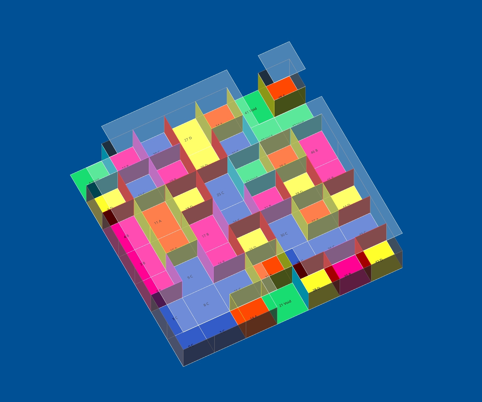
I think just drawing cells as a mesh in Blender is fine, though the software could help a bit more to maintain horizonal and vertical and planar faces. I want the BIM objects to be generated in real time, so you can see the building as you edit the cells.
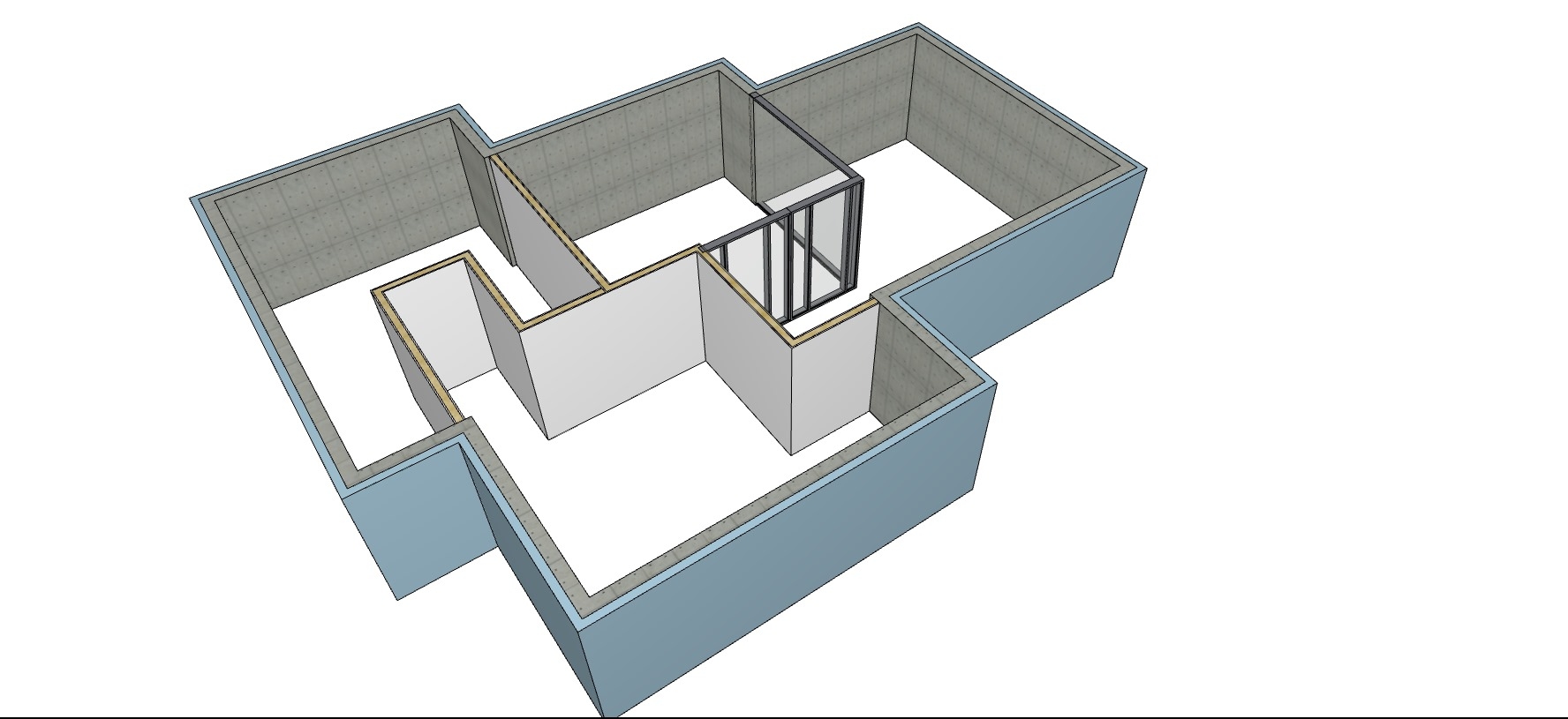
This is very interesting. I notice that you also generate doors and windows automatically. What if it was the user that would draw a face in the cells wall and that would define a door, if you erase the face you'd have an opening without door and a face in a facade would also create a door, if you'd erase the face you'd have a window.
That way user could have an easy way to finetune or shape the cells to place openings, doors and windows and they could be different on exterior walls or interior walls.
I'm also thinking on finishes and structure and how do they relate in BIM.
Imagine a wall that splits two rooms. That wall has a structural layer, like brickwork, and might have different finishes on either side, because each room has it's own finish. The different finishes might represent different layers or thicknessess.
I might be wrong, but the idea I have is that in BIM, when you draw your wall type, you should consider if the type is allowing for the finishes to match what you want on those rooms finishes. The wall type has to change for each room of the building as it is affected by each room finishes and their combinations. However, usually the wall structure type is the same in all the building. So, finishes and their layers, shouldn't be a property that is exclusive from the wall, but that should be also related to a definition from the rooms.
So, for me the ideal process of wall composition is not that the wall type is predefined with all layers or that we have to change it depending on the two adjoining rooms, but that the adjoining rooms have a finishes definition that adds layers to the wall type. If you change finishes in the rooms, the wall type keeps being the same, but the geometry and layers attached to it change.
Wall type brickwork would have a "conscience" of the adjoing rooms and add their finishes to itself. We would only have to state each room finish and what kind of wall structure we would have in the building.
This would also be valid for applying finishes to the building structure models.
If this would be possible, (maybe it's already working like this in some packages, I don't know), it would make total sense to me at a conceptual level, and makes sense from a cell centric model workflow perspective, imho. It also makes sense at a construction level, because at that level you'll have structure in place, and people will then adhere finishes to it.
I don't know if this is making sense, I hope so.