OSArch Community

Designing a new window / door generator

  1. M

    The current parametric window / door is based on the specifications provided by IFC (commonly known as the "Standard Case"). This standard is nice, but I sometimes wonder if it's actually been properly audited by someone who works as a door / window manufacturer or architect who does door / window schedules / details :)

    I think it's now time for Bonsai / IfcOpenShell to be opinionated and offer a new door / window generator using our own rules informed by users to overcome the limitations of the standard case. Ping @yorik who has tackled this many times already in FreeCAD. See https://github.com/IfcOpenShell/IfcOpenShell/issues/3537 and https://github.com/buildingSMART/IFC4.3.x-development/issues/673 and https://github.com/IfcOpenShell/IfcOpenShell/issues/4206 for existing efforts. There are more efforts already but I can't find the link now, and please check out FreeCAD's amazing work too.

    What I'm hoping for:

    1. This will be a door/window generator that can be used purely in the IfcOpenShell API as something we offer. This means FreeCAD can benefit from it too, as well as people who want to generate doors but are dissatisfied (as some of us are) with the standard case. This is not mutually exclusive with other "geometry generation" methods. Just because we offer this doesn't mean we stop offering other methods too.

    2. Doors and windows are similar, and sometimes are combined in real life. FreeCAD actually does treat them as one tool, and I think this is a good idea unless @yorik tells me it was all a big mistakes :) It would be nice to have a macro "cell-based" approach like suggested in 4206, where each (potentially merged) cell either holds a window or a door, etc. Similarly terminology should be shared.

    3. You can either generate a profile extrusion (e.g. for framing) using text/numeric parameterics (e.g. single or double rebate, rebate depth, etc), or by specifying a profile. There must be a logic behind the axis alignment of the cross sectional profile.

    Things I hope for:

    1. I don't like one monster "100 parameters for every possibility". I prefer highly opinionated "Wood frame door" vs "Metal frame door" that has less parameters but tailored for that typical geometry. See for example how we currently do stairs and railings. This may mean there is a "wood generator" or a "metal generator" or a "single door" generator that behaves very differently to a "double door generator" etc. It's simpler to explain and debug.

    2. I'd very much like to also see sliding doors and roller doors be added to our repetoire. Can't do non-residential without them.

    3. Apart from specifying a cross sectional profile extruded along an axis, I don't think we should support other geometry as an input. This obviously places limits (no circular hobbit doors for you!) but that's cool, later on other tools and workflows can be built.

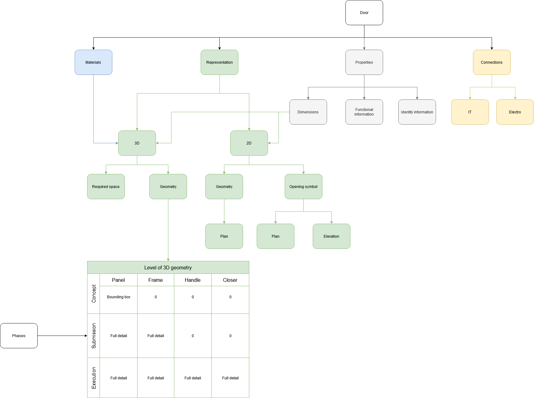
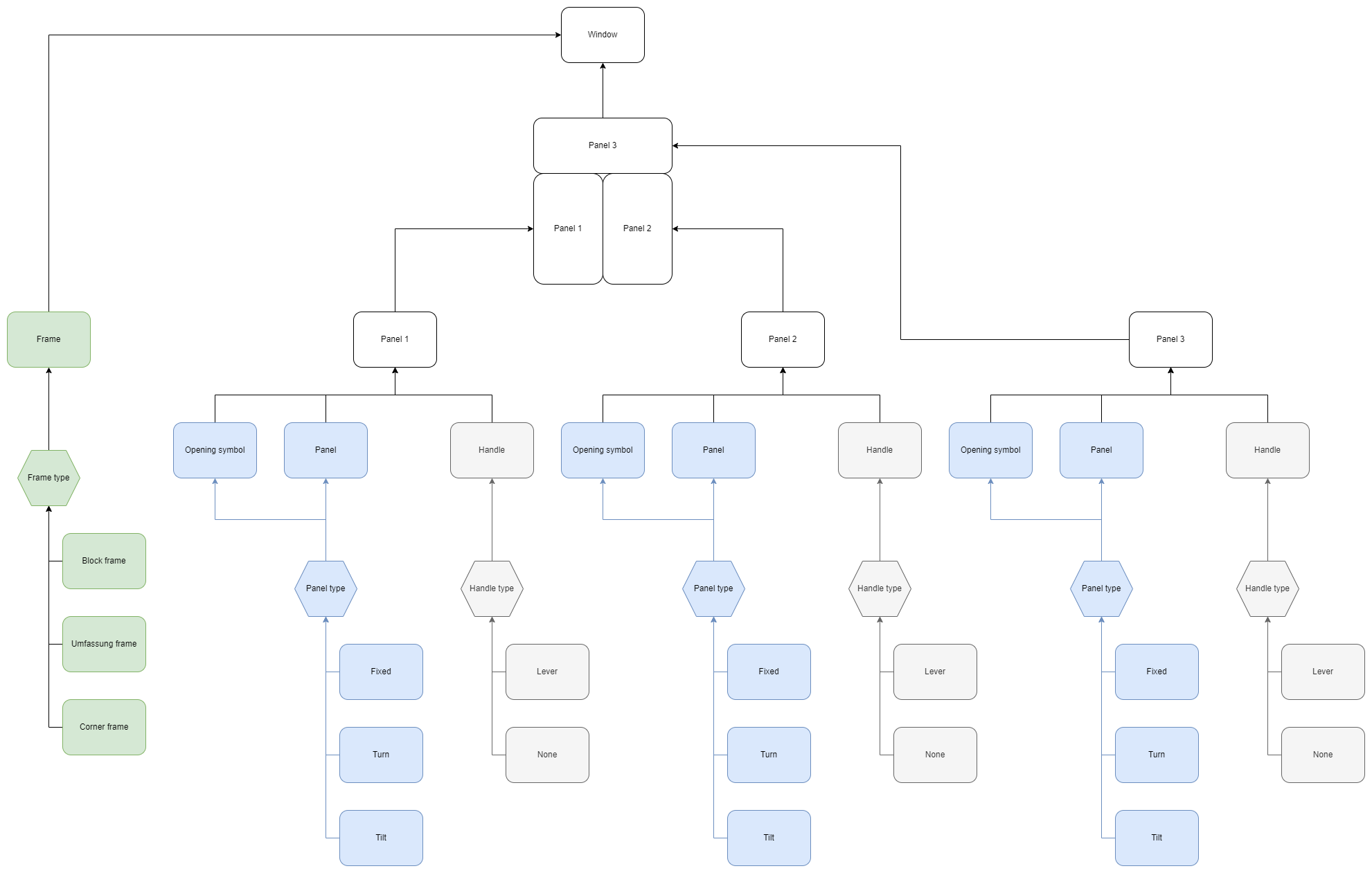
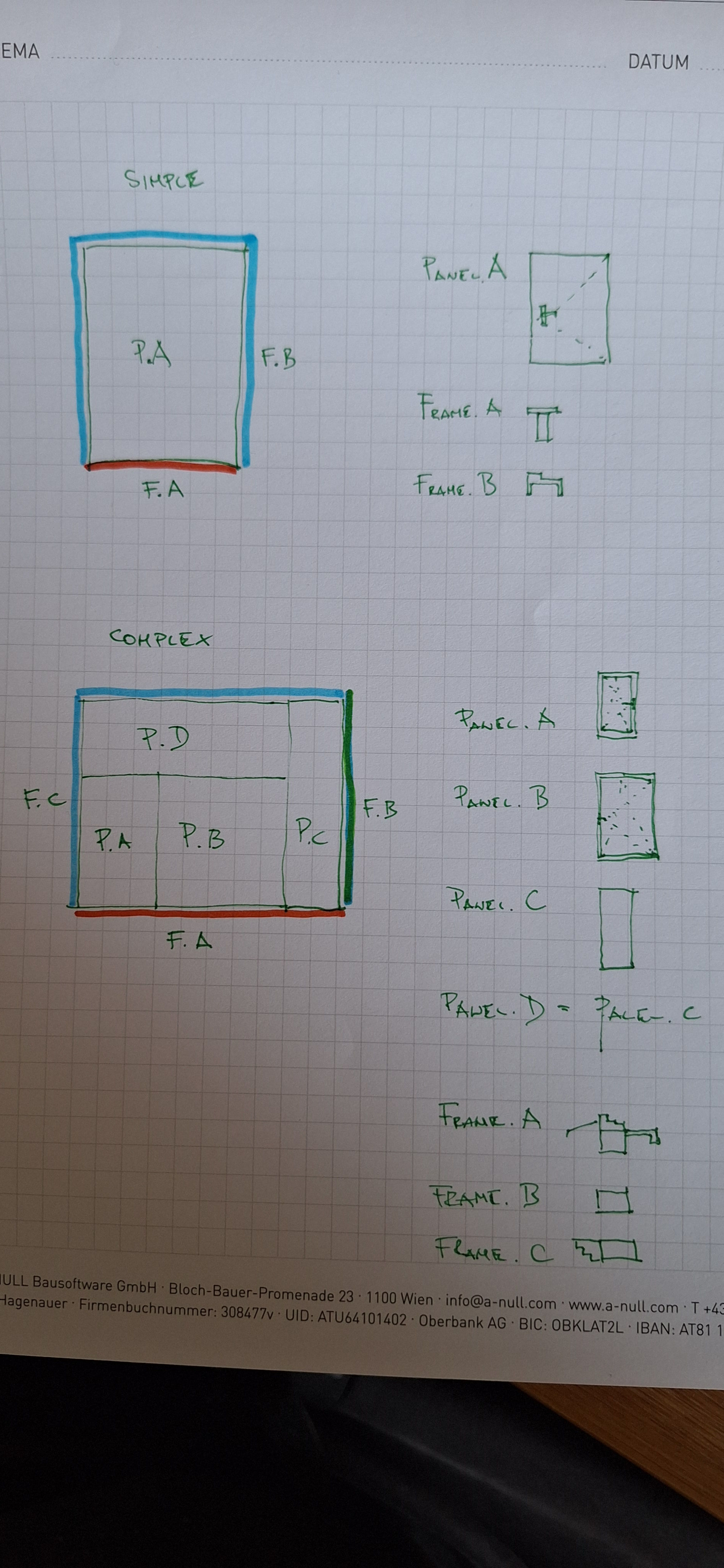
    In order to implement this, I'm hoping for some consensus behind everybody who's ever brainstormed this in the past, and some very nice clear diagrams of parameters that can later be used as documentation.

    Anybody interested in helping take the lead in moderating feedback and generating the diagrams to serve as a specification for this? @Andrej730 has built a super, awesome, shape builder library that means that once we agree on a diagram, the work required into turning this into a parametric IFC shape is potentially quite easy.

  2. M

    In IFC, a "part" would translate to what IFC calls a shape aspect (i.e. named geometry) or constituent (i.e. named material, which correlates with the named geometry). It's basically just a list of geometric shapes that we have named. It's so generic that anybody can reuse these shapes in any context. At this level, it's purely about geometry. Maybe a better name would be a "shape" because it correlates exactly to the IFC concept of shape aspects.

    A simple door/window element (right now) is made out of two shapes: lining and framing. You can see this if you add a new parametric door/window in Bonsai. You could however have a door made out of a framing, panel, vision panel, kick plate, and doorknob. A double swing door has two separate (potentially different) panel shapes. This creates an IfcDoor or IfcWindow.

    A door with a transom be similar, just require more shapes.

    A framed glass door consists of at least two parts (frame, defined by X dimensions + glazing panel, defined by 3 dimensions) so it can have at least two materials.

    Simple vs complex is done best by having multiple geometric representation contexts at different target scales.

  3. V

    As a suggestion, the generator could add a property to set how much the door/window is opened. Currently this needs to be done manually and changes to the generator parameters result in a regeneration of a closed door/window.

    Thanks!

  4. B

    @vdl said:

    As a suggestion, the generator could add a property to set how much the door/window is opened.

    Yes, the windows and doors should be able to rotate about the hinge axis without rewriting the entire representation - and they should open and close as you explore a building in 'walk mode'.

  5. N

    I would first think about the 'hole in the wall' define that, then think about how that hole is finished, i.e. jamb/framing then think what is going in the hole in the wall. It could be a window of various configurations and/or a door(s) or it could just be an opening in the wall or perhaps we could include recesses in walls too

    Hopefully I have a little time at work tomorrow to draw some diagrams to share :)

  6. Y

    This is a big task :) I'm actually in the middle of refactoring FreeCAD's own window/door tool. Basically following https://yorik.uncreated.net/?blog%2F2023-025-new-window-tool

    Basically I think:

    • Combining doors and windows is an excellent thing, never gave any problem, and they are 99.9% similar code-wise. The only thing we've changed, is that people really like having two different buttons, because in our mind, a door is a very different concept than a window. So basically, two buttons with two different sets of presets, but both using the same tool internally.

    • If we go deep into windows, then people will want very customizable windows with very wild things and parts. This is out of the scope of a single tool that builds windows based on parameters. In FreeCAD we solved that by allowing you to build windows from any kind of 2D shape, whose polyloops can be extruded into "window components" (frames and panels). This proved to be extremely versatile, people can design almost anything just like with revit's families designer.

    • Now, we are both extending this (allowing to insert custom window components made with other tools/workbenches) and simplifying this (allowing to define simple components from simple parameters such as height, width and thickness, without a 2D shape).

    • So to resume the above, what works very well for us is to make the window an assembly of "window components". This works well UX-wise (variety of ways to define these components, from very simple to very complex) and IFC-wise (each component is decomposable individually) and is very preset-friendly. And a lot of further interaction can be added to these components (what defines an opening, what must move and what must not, etc...)

    • In FreeCAD, each window component has:

      • a name

      • an optional base object (sketch, 2D object, or even a solid)

      • a type (frame, solid panel, transparent panel, louvred panel)

      • an optional parent component (in which case it moves together)

      • a list of wires/polyloops (to be taken from the base object, if it's a 2D shape) or a definition such as (x,y,length,width,thickness), if there is no base object

      • an extrusion value

      • an optional offset to be applied before extruding

      • an optional edge that describes a hinge (hinged opening) or a translation (sliding opening)

      • an opening mode (90° rotation, sliding, etc...), if a hinge is defined

    • The window object itself contains basically a list of components, an extrusion direction, plus a few cosmetic things. Also a percentage of opening so the window can "really open" in the model :)

    I'd be thrilled to try to build something common together, directly in IfcOpenShell!

  7. J

    I'd start on a more abstract level.

    Here's a diagram on information needed for a BIM model of a door:

    It's the structure of the green part we are discussing here. Some questions to consider:

    1. How do we handle the design phases (the table)? In my opinion we should have different object for different phase.

    2. A door is actually an assembly of typical parts (headers in the table). In my opinion it should be possible to manage these parts separately. (So that I don't have to change the whole object just to add a different type of handle)

    3. Where is the line between a door (a window) and an assembly? This is the main difference between doors and windows in central Europe and the topic that makes this so difficult. Doors are straightforward (one or two panels+frame+handle is a door, everything else is an assembly), windows are complex (all modern windows have the same frame, but a window can have any combination of multiple panels, each being fixed or turning or tilt)

  8. J

    And here are diagrams illustrating #3:

    3D geometry of a door:

    3D geometry of a window:

  9. M

    It sounds as though what's being suggested here is that "build a door tool" is the wrong way to go. Instead it should be more like "build-a-bear" (maybe this is a terrible analogy) where you can "build a doorknob", "build a frame", "build a panel", "build a louvre" and then finally assemble "component ABC at coord XYZ". So perhaps IfcOpenShell could build this series of mini-objects?

  10. K

    Door openings, window openings, and window partitions are in the IFC document. It would be nice if some of these settings match IFC, along with handles, frames, etc :)

    https://ifc43-docs.standards.buildingsmart.org/IFC/RELEASE/IFC4x3/HTML/lexical/IfcDoor.htm

    https://ifc43-docs.standards.buildingsmart.org/IFC/RELEASE/IFC4x3/HTML/lexical/IfcDoorTypeOperationEnum.htm

    https://ifc43-docs.standards.buildingsmart.org/IFC/RELEASE/IFC4x3/HTML/lexical/IfcWindow.htm

    https://ifc43-docs.standards.buildingsmart.org/IFC/RELEASE/IFC4x3/HTML/lexical/PEnum_WindowPanelOperationEnum.htm

    https://ifc43-docs.standards.buildingsmart.org/IFC/RELEASE/IFC4x3/HTML/lexical/IfcWindowTypePartitioningEnum.htm

  11. P
    • In FreeCAD, each window component has:
    • a name
    • an optional base object (sketch, 2D object, or even a solid)
    • a type (frame, solid panel, transparent panel, louvred panel)
    • an optional parent component (in which case it moves together)
    • a list of wires/polyloops (to be taken from the base object, if it's a 2D shape) or a definition such as (x,y,length,width,thickness), if there is no base object
    • an extrusion value
    * an optional offset to be applied before extruding
    * an optional edge that describes a hinge (hinged opening) or a translation (sliding opening)
    • an opening mode (90° rotation, sliding, etc...), if a hinge is defined
    • The window object itself contains basically a list of components, an extrusion direction, plus a few cosmetic things. Also a percentage of opening so the window can "really open" in the model :)

    It appears to me these are more or less a practicing Architect would be interested during schematic and detailed design stage. There were discussions probably a few more attributes or components might be interested, e.g. finishes of panel, frame, vision panel (inside/outside), ironmongery (like lock/handle, hinge, closer, selector appearance / type), materials and appearance, fire rating (intumescent strip and smoke seal details) , otherwise more detailed information would be fabricator's expertise.

    To this end, there are features and efforts in FreeCAD when provides the flexibility to build complex door shape - though not sure how and if FreeCAD / IFC may support e.g. door lock/handle type shape).

    Another item which interest me is Stairs in FreeCAD which I am trying to have another look to refactor and provide more flexibility and features to build more complex and probably freeform stairs.

  12. M

    In contrast to the complexity, I'd also prefer an option of a purposely limited but basic, few parameters, early-schematic door/window that "just works".

    BTW @KoAra yes, the current implementation completely follows the IFC standardcase. For this one, any shared concepts should also share terminology.

  13. D

    @Moult said:

    It sounds as though what's being suggested here is that "build a door tool" is the wrong way to go. Instead it should be more like "build-a-bear" (maybe this is a terrible analogy) where you can "build a doorknob", "build a frame", "build a panel", "build a louvre" and then finally assemble "component ABC at coord XYZ". So perhaps IfcOpenShell could build this series of mini-objects?

    This would certainly be appealing if feasible. Build a doorknob that you can use as both a doorknob or a window handle, build a frame that can be used for a window, door, or a simple opening; define a louvre for all openings on a building. Then combine all those "presets" into a full doors or windows assemblies, instance the knobs on the opening parts at a configurable position.

    If we could modularize those at UI level too, then a full door object would have say a Frame UI panel with the frame settings, a _Paneling _UI panel with the paneling settings, a knob placement UI with a list to pick from designed knob presets, etc. A window object could then recycle the same UI modules (frame, panels, knob placement).

    A simple opening without door or window but with a frame could use the same Frame UI to set the jambs. Maybe the Paneling UI could eventually be used to design wall panels or a wainscot.

    The downside of this approach other than implementing it, is that the UI for a full blown opening will have a complex UI, but I suppose if we want a comprehensive tool we'll always end up with one anyway. To mitigate this, a new base opening could have a simple base UI that would generate a good default, then users would add complexity, as desired to not overwhelm from the start.

  14. T

    Great to see this post come up! @Moult, I’d be happy to contribute or even take the lead in moderating inputs for the specification. We touched on this briefly last year, and since then, I’ve conducted quite a bit of research that I’d love to share. I really see the value in your “build-a-bear” approach. As an architect, I want to define my frame and panel types once and be able to reuse them multiple times when creating door assemblies. I’d rather not have to re-enter the same parameters for different door types that share common frame or panel configurations, as this can lead to errors.

  15. M

    @tim go for it, please take the lead :)

    Can I request that even if we do end up with a more complex but powerful modular build-a-bear set of generators, can we also agree upon a simple but limited variant? Something that new users will see like "oh, here's a door" and not have to consider much more especially for early stage design.

    In terms of timing, the next release date is 5th April, so if there was some consensus (doesn't have to be finalised, after all we'll learn by doing) in about 2 weeks, that'll give another 2 weeks to flesh together a working prototype we can play with and release in this cycle.

  16. T

    Thanks, @Moult. I agree, it’s important to balance a powerful modular system with a simple, user-friendly version for new users, especially in early design stages.

    The timeline works for me. I’ll be offline for a bit as I’m about to board an international flight, but please keep the ideas coming and I’ll catch up as soon as I can.

  17. T

    I'm a bit jet-lagged and still catching up on the useful information above but unless there are strong objections, it seems we're moving forward with a component-based approach for a combined door-window assembly generator. I like this direction as it balances ease of use with customizable complexity—keeping the top level simple while allowing detailed parameters within components. This should also lead to lightweight yet powerful schedules, ensuring intricate details (e.g., door frames) don’t unnecessarily inflate every instance in a model.

    Based on the discussion so far, our core components appear to be:

    Frames

    Panels (including panes, and louvers)

    Sills and Thresholds

    Casings

    Hardware

    Are we missing anything?

  18. N

    Hi @tim glad you have volunteered to take the lead on this important development . from the above conversation I understand the proposal is simple / complexed. Simple is basically parametric, define the door leaf/panel, size and location. Then jamb/frame, size of the profile and starting origin of the sweep, around the left, top and right of the leaf, in relation to the void origin. The void is calculated by the door panel/leaf size and jamb/frame size. We also need to locate the axis of the door handle, this is an offset in the X from the strike side of the door, from the base of wall/floor in the Z and to face of leaf, then mirrored. Also on the Simple door we should include double doors, equal size panel/leaf and unequal. The I think once this proof of concept is done then we would add sliders, face and cavity/pocket. A third option is simply a hole in the wall with frame/jamb detail. The hole in the wall could have a recess option as well. The third stage is to add the ability to make bespoke and complexed doors, shape and style. On the subject of placement from a user perspective it is help to place a door or opening with options of left centre or right side snapping to the wall and also to the 3dcursor. Additionally at the point of insertion determining which of the 4 swing direction is a time saver. I'm sure there's more to add, but I'm on my phone at the pub so later. Thanks for reading :)

  19. T

    @Nigel thanks for your thoughts! My intention is not to lead us toward creating separate "simple" and "complex" versions but rather to structure the values into required and optional parameters. The required values would define a straightforward version, while optional parameters would allow for more complex configurations. We can also assist users by providing sensible default values that rarely need adjustment.

    A key goal for me is ensuring that the simpler version remains accurate for the values it represents. I really like the idea of letting users define door panel dimensions, as I see this as a fundamental shortcoming in the current parametric door system.

    Regarding the sweep definition, I agree with your approach. To ensure the door assembly and void are accurately represented, there should be a small gap between the inside of the frame and the door panel - something we can handle with a sensible default.

    I see this as an iterative process—diving deep into the details while continuously zooming out to ensure clarity and usability. Double doors, sliding doors, and cased openings are all important and can be built out progressively, with each type filtering applicable values.

    I also like the idea of controlling placement at insertion (snapping left/center/right), but we should stay focused on the specification for now rather than the implementation.

    Your comment regarding swing direction is interesting. I don't know if there is a limitation with IFC that means we can't mirror a door type and handle the swing direction on the instance, rather than creating a type for each swing direction. Does anyone with more experience in this area know if IFC allows for this approach?

    Similarly, defining door handle positioning parametrically makes sense and I would cover this in the hardware section.

    Feedback and input welcome.

  20. M

    Anything that is mirrored is a different type in IFC.

  21. N

    @tim I was thinking of the simple/complexed in one tool but where the complexed option is 'hidden' until the user chooses to reveal all the options. Like how some photocopiers provide a decluttered interface, not sure if I'm explaining myself well. Some BIM apps have dozen settings when all the user wants to do is insert a simple door, we want to entice new users in.

    The actual user options like placement methods can come later, I just had to get it out of my head, same with being able to save our preferences for door settings.

  22. S

    slightly off-topic

    how to set IfcWindowPanelOperation in Bonsai? it's in Pset_WindowPanelProperties.OperationType

    thanks

  23. Y

    @tim said:

    Frames

    Panels (including panes, and louvers)

    Sills and Thresholds

    Casings

    Hardware

    This looks good, and we could mimic this in FreeCAD. We have separate items for transparent and non-transparent panels, because it allows us to represent a window correctly even without materials applied (otherwise it's not possible), and for louvers because it uses a different function to draw the geometry. Maybe there could also be a "Custom" or "Undefined" category?

  24. J

    So after giving it some thought my proposal is a kind of a curtain wall approach:

    1. the first parameter to choose is the 2D topology - a 2D sketch which defines panels, frames and their naming

    ** OverallWidth, Overall Height has to be defined every time, other properties are defined by the elements of the topology

    ** by selecting a simple topology you get a primitive element with a no parameters, by selecting a different one you get a complex element

  25. J

    Here are the drawio schemes @tim

  1. Page 1
  2. 2

Login or Register to reply.