OSArch Community

Designing a new window / door generator

  1. T

    @yorik said: This is a big task :)

    You don't say.

    Where to begin. After spending the past few days reading, digesting, organizing my thoughts, then unorganizing and reorganizing my thoughts again, I’m ready to contribute some structure to the discussion. My main goal is to keep this project focused and avoid drifting into curtain wall territory, that would be a valuable project in its own right.

    To keep things contained, I’ve compiled a set of common door arrangements, including doors, sidelights, and transoms. I’ve structured them into a 3 × 2 grid, which I believe covers the majority of use cases for both doors and windows. Does this approach make sense to others?

    Common door arrangements

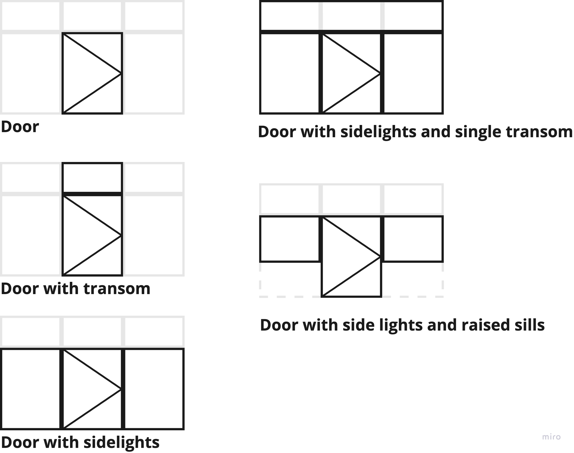
    I think a 3 x 2 grid would cover the majority of use cases for doors and windows, but what do others think?

    The key challenge is defining a set of parameters that covers the:

    • Layout of the general arrangement

    • Selection of components

    • positioning of its components.

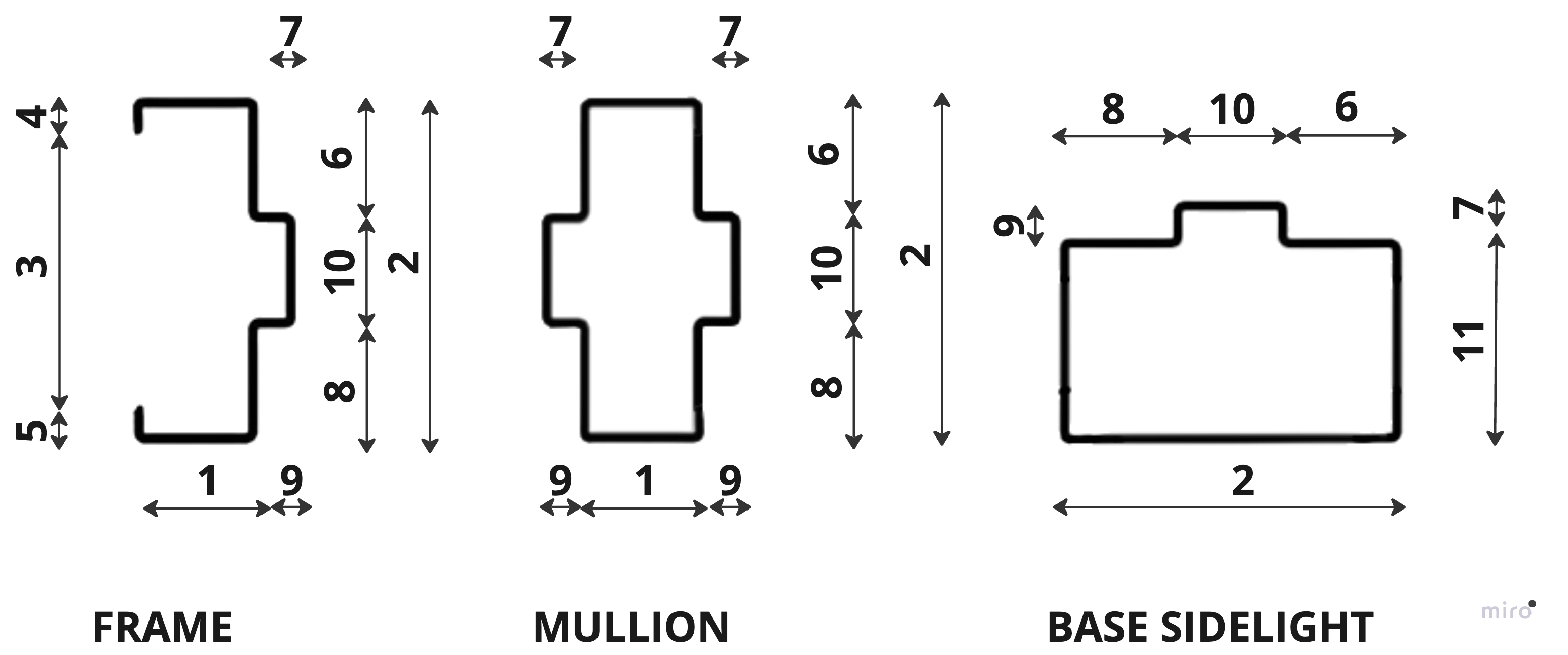
    As I started breaking down the key components of a parametric door, it became clear that door frames need more attention. Right now, hollow metal frames, a standard in commercial construction, are missing from the current system. At first, I thought we needed separate definitions for wood vs. metal frames, but after digging deeper, I realized that the fundamental parameters are the same across all frame types, the main difference lies in material and fixing method.

    Instead of defining individual frame members, my proposal is to introduce a Door Frame Set at the assembly level, consolidating all necessary parameters in one place. This approach makes the system more structured and easier to use, while still allowing for key adjustments where needed.

    Below is my proposal for Door Frame Set parameters. A similar approach would apply to window frames, with their own dedicated parameter set.

    Door Frame Set

    Designed for Single Rebate, Double Rebate, Double Egress, and Cased Opening frames.

    Suitable for Wood and Metal frame profiles

    Designed to accommodate face-fixed, wrap-around, and flanged frame-fixing methods (fixing details such as flanges, anchors, and straps are not included).


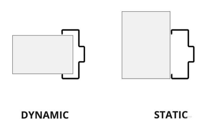
    Supports dynamic depth adjustment based on wall thickness. Alternatively, a fixed depth can be set manually.


    Properties

    Name: User-defined

    Description: User-defined

    Material:

    Dimensions

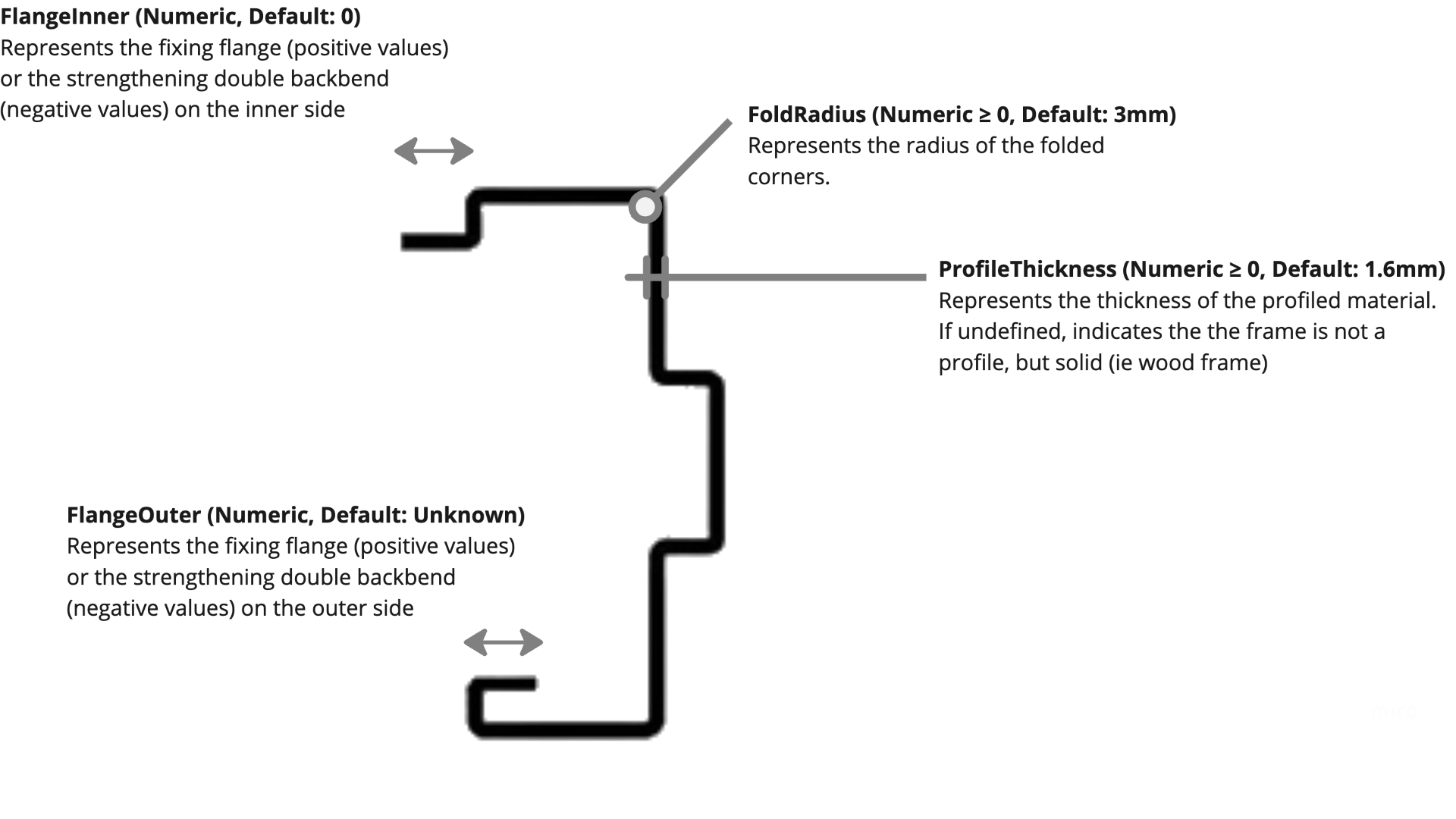
    1. Thickness (Numeric > 0, Default: Undefined)
Defines the thickness of the door frame.

    2. Depth (Calculated: ProjectionInner + Throat + ProjectionOuter)
Total depth of the door frame, measured perpendicular to the door face. This is a calculated value and cannot be overridden.

    3. Throat (Numeric > 0, Default: Undefined)
Represents the depth of the throat opening. If Undefined, it dynamically adjusts to match the wall thickness.

    4. ProjectionInner (Numeric ≥ 0, Default: 13mm)
Extends the frame outward from the inner side wall face.

    5. ProjectionOuter (Numeric ≥ 0, Default: 13mm)
Extends the frame outward from the outer side wall face.

    6. RebateFaceInner (Numeric ≥ 0, Default: 0mm)
Defines the width of the rebate face on the inner side. Typically set slightly larger than the door panel width to accommodate mounting and gaskets. If 0mm, no rebate is created on the inner side.

    7. RebateDepthInner (Numeric ≥ 0, Default: 15mm)
Defines the stop depth on the inner side of the frame. Only applies if RebateFaceInner > 0.

    8. RebateFaceOuter (Numeric ≥ 0, Default: Undefined)
Defines the width of the rebate face on the outer side. Typically set slightly larger than the door panel width to accommodate mounting and gaskets. If Undefined, it defaults to RebateFaceInner. If 0mm, no rebate is created on the outer side.

    9. RebateDepthOuter (Numeric ≥ 0, Default: Undefined)
Defines the stop depth on the outer side of the frame. Only applies if RebateFaceOuter > 0. If Undefined, it defaults to RebateDepthInner.

    10. Soffit (Calculated: Depth - RebateFaceInner - RebateFaceOuter)
Represents the remaining frame width after subtracting the rebate face dimensions from the total frame depth.

    11. BaseSidelightThickness (Numeric ≥ 0, Default: Undefined)
Defines the thickness of the frame at the base of the sidelight. If Undefined, it defaults to Thickness

    In the current IFC door lining properties, the frame depth can adjust dynamically to match the wall depth in which it’s placed. This proposal relies heavily on that behavior. I’m unsure how difficult this would be to implement, as Bonsai doesn’t yet support it, but if we could achieve it, it would be a game changer. Would love to hear thoughts on this approach!

  2. M

    Can I advise having three separate systems:

    • a kit of parts. Essentially a list of parts and the dimensions that define them.

    • element definitions. This is preset defining how a list of parts can come together to make a single semantic element (e.g. door, window, member, plate, etc)

    • aggregate systems. A system defining how multiple elements can be arranged to make a bigger thing. E.g. curtain walls, panellised systems , stick build systems, arbitrary grids of things...

    For example, a single part might be a solid panel, defined by 3 dimensions, width, height, and thickness. Another part might be a door frame, defined with 10 dimensions. Notice how at this point, we don't care if the dimensions are automatic or manual. We can spec super quickly all sorts of things from kick plates to vision panels to door knobs. This is also reusable across any future casework, joinery, or similar. This can be 2d or 3d.

    Then an example super simple element definition is just a panel, frame, and their relative insertion points.

    Then, an aggregate system will define the elements it is compatible with and how it assembles it together. This is where automatic dimensions to fit the frame dimensions etc come into play. For example your 3x2 grid is in this category.

    This separation reflects how things work in the real world, and also allows us to iterate from simple to more complex. Notice how they also match IFC... each part in the kit of parts is a shape aspect, each element is an IFC element, each aggregate is an aggregate. This part, element, aggregate approach can also work in the future with furniture, railings, fences, stairs...

    If we make mistakes, we can redesign each of these 3 systems separately to minimise risk.

  3. M

    To accommodate the different fixing methods, the part itself remains unchanged, only the element or aggregate system needs to know this (to offset the frame).

    If parts are all separate, we can allow users to define one material per part. That gives us one less thing to worry about.

    I like the parameters you've come up with for frames and they match my experience doing door details. I assume although you're drawing a profile, this will be swept left, top and right edges for a door frame?

    Do you think any changes if it becomes core filled?

  4. T

    @Moult thanks for the detailed breakdown, it’s really helping to clarify how these components fit together. Here are a few thoughts and questions on the system you described:

    • a kit of parts. Essentially a list of parts and the dimensions that define them.

    Would it make sense for every "part" to have at least a Name and Description, while Geometry remains optional? Would a part also require a classification, or would this not be required at this level - ie should a door knob know it is a door knob or is it just a part with a name?

    • element definitions. This is preset defining how a list of parts can come together to make a single semantic element (e.g. door, window, member, plate, etc)

    I’m not entirely sure I follow the list of examples here. Since the goal is to generate doors and windows, how do members and plates fit into this system? Are they placeholders for future expansion, or do they play a role in the current scope?

    • aggregate systems. A system defining how multiple elements can be arranged to make a bigger thing. E.g. curtain walls, panellised systems , stick build systems, arbitrary grids of things...

    For example, a single part might be a solid panel, defined by 3 dimensions, width, height, and thickness. Another part might be a door frame, defined with 10 dimensions. Notice how at this point, we don't care if the dimensions are automatic or manual. We can spec super quickly all sorts of things from kick plates to vision panels to door knobs. This is also reusable across any future casework, joinery, or similar. This can be 2d or 3d.

    This is the part I am most excited about. In most architectural software I’ve used, door frame dimensions are defined at the "element" level, which means the same frame dimensions need to be manually assigned across multiple element types. Separating them as independent parts seems like a more modular and reusable solution.

    Then an example super simple element definition is just a panel, frame, and their relative insertion points.

    Then, an aggregate system will define the elements it is compatible with and how it assembles it together. This is where automatic dimensions to fit the frame dimensions etc come into play. For example your 3x2 grid is in this category.

    Thanks for the clarification. I initially thought my 3x2 examples were considered simple elements, but I see now that it falls under an aggregate system. So, for example, a door with a transom would consist of:

    • A frame set element (encompassing the top, sides and transom/door head mullion)

    • A frameless door element

    • A glass pane element

    Does that breakdown align with what you're describing?

    To accommodate the different fixing methods, the part itself remains unchanged, only the element or aggregate system needs to know this (to offset the frame).

    If parts are all separate, we can allow users to define one material per part. That gives us one less thing to worry about.

    Would be nice, but I think for parts like framed glass doors, we will need two materials.

    I like the parameters you've come up with for frames and they match my experience doing door details. I assume although you're drawing a profile, this will be swept left, top and right edges for a door frame?

    In my workflow, as long as the frame Name can be scheduled and the profile can be drawn once in a detail, I don’t necessarily need a complex 3D sweep, just a simple rectangle would be sufficient. However, there have been some com documentation phase. Would there be a way to support both simplified and high-detail representations based on workflow needs?

    Do you think any changes if it becomes core filled?

    If needed, the user could simply assign a different material e.g. "Core-Filled Metal Frame" instead of "Hollow Metal Frame", rather than adding complexity to the part itself. Would that approach work within this framework?

  5. J
    • a kit of parts. Essentially a list of parts and the dimensions that define them.

    Would it make sense for every "part" to have at least a Name and Description, while Geometry remains optional? Would a part also require a classification, or would this not be required at this level - ie should a door knob know it is a door knob or is it just a part with a name?

    Classification. Naming stuff getss messy super quickly.

    Then, an aggregate system will define the elements it is compatible with and how it assembles it together. This is where automatic dimensions to fit the frame dimensions etc come into play. For example your 3x2 grid is in this category.

    Thanks for the clarification. I initially thought my 3x2 examples were considered simple elements, but I see now that it falls under an aggregate system. So, for example, a door with a transom would consist of:

    • A frame set element (encompassing the top, sides and transom/door head mullion)
    • A frameless door element
    • A glass pane element

    Does that breakdown align with what you're describing?

    This is my biggest issue with your suggestion @Moult - as I said, where I live, most (all) people would get very upset to see a door with a transom or a 3x2 window as an aggregate. This is supposed to show up as a single element in a schedule.

    I like the parameters you've come up with for frames and they match my experience doing door details. I assume although you're drawing a profile, this will be swept left, top and right edges for a door frame?

    In my workflow, as long as the frame Name can be scheduled and the profile can be drawn once in a detail, I don’t necessarily need a complex 3D sweep, just a simple rectangle would be sufficient. However, there have been some com documentation phase. Would there be a way to support both simplified and high-detail representations based on workflow needs?

    We definitely need multiple detail levels for 3D in Europe, as I wrote above. My prefered workflow would be having an element with simplified geometry for design phase which can be easily switched for a more complex one (and back! This is an issue on its own).

    Do you think any changes if it becomes core filled?

    If needed, the user could simply assign a different material e.g. "Core-Filled Metal Frame" instead of "Hollow Metal Frame", rather than adding complexity to the part itself. Would that approach work within this framework?

    If I'm correct, ifc doesn't allow mixing 2D and 3D representations as revit does. This means for 3D Model representation it doesn't matter, it only matters for 2D.

  6. M

    Sure, I guess the core suggestion is that there are things that can be designed separately, that each build up open the previous thing, and that they exist as a concept in IFC.

    1. Shapes

    2. Elements

    3. Aggregates

    I was wrong to suggest that things like gridded arrangements must occur at an aggregate level. It should definitely be possible to have a single door element generator that has rules to handle a 3x2 grid for both glazed and door panels.

    I only mention aggregate to be aware that in the future curtain walls are made out of windows, doors, air terminals, members ... etc.

  7. T

    Simple vs complex is done best by having multiple geometric representation contexts at different target scales.

    I agree (though others may have different views) that the best way to handle simple and complex representations is through multiple geometric representation contexts at different target scales. The question is—should additional details be captured within the shape definition itself, even if they aren’t always used in certain representations, such as a 1:100 drawing?

    For example, in the image below, these profile details could be defined within the shape but only activated when a higher-detail scale is required.

    If this is the right approach, I was thinking that three predefined increments might be sufficient:

    • 1:5 and below (high-detail representation)

    • Above 1:5 up to and including 1:50 (moderate detail)

    • Greater than 1:50 (simplified representation)

    Alternatively, should these increments be user-defined for more flexibility? What do people think?

  8. N

    @tim user defined, I may not want to have anything but a simple rectangle at any scale whereas others may for perfectly valid reason want ten options. Also in the world we use 1:10 1:50 etc but freedom units have 1 inch equals a foot or something like that so even the scale naming needs to be user definable

  9. N

    @tim when you say 'multiple geometric representation contexts' what does that mean as I took it to mean changing levels of detail at different scales or is it something else?

  10. T

    Yeah, that was probably a bit misleading - the implementation in Bonsai can come later. For now, I just wanted to gauge whether defining detailed elements at the "shape" level is a good approach. Personally, it makes sense to me, but I’d love to hear if others see any drawbacks. Also, good to know that user-defined scales are the preferred approach.

  11. J

    I know "target scale" comes from ifc, but I believe "target design phase" would be more appropriate:

    • 3D views don't have a scale

    • Sometimes you need 1:100 in early design, sometimes it is enough for construction, but the detail level needs to be different

    @tim said:

    Yeah, that was probably a bit misleading - the implementation in Bonsai can come later. For now, I just wanted to gauge whether defining detailed elements at the "shape" level is a good approach. Personally, it makes sense to me, but I’d love to hear if others see any drawbacks. Also, good to know that user-defined scales are the preferred approach.

    I'm still not sold on packing everything in a single element (what Revit does) it leads to bloated models and confusion in the early design phases, because you have 20 different types of doors you have to choose from, even though the information is irrelevant in that early design phase and you want to leave it out.

    As I said I'd prefer having a primitive "design phase door" and be able to easily switch it to a more complex one later.

  12. N

    @JanF ... and be able to easily switch it to a more complex one later. That is a very appealing idea

  13. T

    The complex window/door divisions in some of the sketches surely require a graphic interface. Maybe it's more feasable to pick from a list of enumerated partitions.

    Regarding scale let me quote the (UK) National Bim Standard:

    The object should be modelled with geometrical detail that will not compromise the BIM model when used in practice. To avoid over-modelling, follow the principle of not modelling elements of a product that will not be seen.

    The same NBS source proposes Boolean Yes/No to deal with information on accesories that don't need to be modelled (from attached shared parameter file) e.g.: HasLock, HasGrabHandles, IsLaminated, SelfClosing; hasPanic, TripleGlazing, IsWired, DoorSeal...

  14. J

    @tlang said:

    The complex window/door divisions in some of the sketches surely require a graphic interface. Maybe it's more feasable to pick from a list of enumerated partitions.

    Ha, cool, didn't know this existed. But I'd still prefer a graphic interface.

    The same NBS source proposes Boolean Yes/No to deal with information on accesories that don't need to be modelled (from attached shared parameter file) e.g.: HasLock, HasGrabHandles, IsLaminated, SelfClosing; hasPanic, TripleGlazing, IsWired, DoorSeal...

    I'm not a fan of booleans for properties that generally require more detail. For example HasLock - pretty much all doors have some kind of lock, but what kind? IsLaminated is one of maybe twenty different possible surfaces, in Europe we have at least three types of panic handles, three types of closers and so on.

  1. Page 1
  2. 2

Login or Register to reply.