I think this video is still useful to get started with drawings in BlenderBIM:
Thanks @bruno_perdigao !
@bruno_perdigao said:
I think this video is still useful to get started with drawings in BlenderBIM:
Unfortunately i dont think that video is good to start on. I had the same path and it turned out the creation and modelling features in that video are obsolete now.
@strumet said:
@Nigel said:
Hi @strumet I set up some standard views ortho camera, plans sections elections. It would be awesome to batch export to SVG rather than one at a time, what do you think?
Hi @Nigel,
I added multiple cameras support.
The feature will be in the next release but if you'd like to try it already you can find a pre-release here attached.
And thanks for your help!
@strumet
Nice! that is especially useful.
Thank you so much
@Constantinesis said:
I had the same path and it turned out the creation and modelling features in that video are obsolete now.
They are very obsolete
@Constantinesis said:
@bruno_perdigao said:
I think this video is still useful to get started with drawings in BlenderBIM:
Unfortunately i dont think that video is good to start on. I had the same path and it turned out the creation and modelling features in that video are obsolete now.
I was referring to the drawing features specifically. I was able to reproduce some of the steps shown in this video.
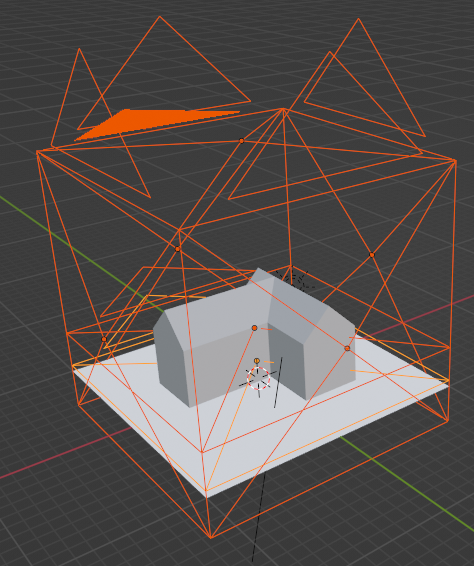
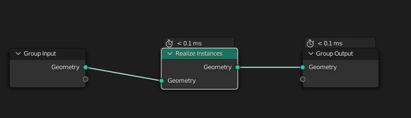
Hello @strumet , FWIW the meshes that did not export were mesh instances resulting from a geometry nodes tree. They do not get instantiated by the Convert to > Mesh operator if the instances or not "Realized". My solution is to add a "Realize Instances" node tree to every object dealing with instances before evaluation.
Also, setting the scale any lower than 1:50 causes some kind of overflow and the export process never finishes. Might be a "me" problem though.
Cheers
Thanks @Gorgious.
Actually, I didn't consider the meshes that are resulted from a geometry nodes tree. My bad. I need to fix it in future versions.
About the scale problem it's probably caused by the rendering process I told you in my previous post. I should figure out another way to determine objects visibility. Anyway, if you are not interested in svg drawings (which are actually scaled), you can keep the scale at a low value (like 1:200 or 1:100): as a matter of fact, dxf or dwg are always drawn 1:1
Hello there @strumet ,
I've submitted a PR to be able to copy prj settings between different objects.
https://gitlab.com/marzof/prj/-/merge_requests/1
I think this kind of solves my other issue https://gitlab.com/marzof/prj/-/issues/4
Cheers
Thanks Gorgious,
Wow, I'm really impressed! Let me check your PR (in gitlab they are called MR, as merge request) in order to merge it.
Anyway I have to apologize for the delay in replying to your issues: I didn't receive any notification from gitlab...
In the meantime I fixed the issue #3 about same block name in a cad drawing. I hope it's working now.
Perfect!
I merged your MR: now prj v0.0.9b contains both fixes to your issues.
Thank you so much!
Well, thank you for your work, you're saving me and my computer a lot of time and sweat !! No need to apologise for the lack of immediate response, I figured you had other things on your plate and you'd eventually see it. :p I know I did and still do, so all is well.
I have to say that I really like the structure of your addon, everything is really neat and tidy. I found the relevant bits to piece together really easily. High five :)
If you're okay I'm down to add things here and there when I feel they're worth it while I'm using it. I think I'm going to be using it a lot for work in the coming weeks & months. Also, 3.3 brings a swathe of improvements to the line art modifier so I'm eagerly awaiting the stable release to jump up on it !! https://wiki.blender.org/wiki/Reference/Release_Notes/3.3/Grease_Pencil
Cheers
Edit : Really glad for this commit too ! https://gitlab.com/marzof/prj/-/commit/bde9407288ece6ab5a90610628f689388b599177 I'm going to test it as soon as possible, this was one of my other issues with usability.
@Gorgious said:
[...] No need to apologise for the lack of immediate response, I figured you had other things on your plate and you'd eventually see it. :p I know I did and still do, so all is well.
Sure... I'm just surprised that the notification system in gitlab didn't work (even if I was busy I would have replied you anyway in order to give you a feedback). I just made some changes in gitlab settings and I hope it works now.
I have to say that I really like the structure of your addon, everything is really neat and tidy. I found the relevant bits to piece together really easily. High five :)
Glad to hear that!
If you're okay I'm down to add things here and there when I feel they're worth it while I'm using it. I think I'm going to be using it a lot for work in the coming weeks & months.
I'm totally ok with that!
(for the moment I'm trying to allow users to disable visibility calculation to avoid rendering calculation during the process... as you pointed out it could increase drawing time significantly or even cause crashes)
Also, 3.3 brings a swathe of improvements to the line art modifier so I'm eagerly awaiting the stable release to jump up on it !! https://wiki.blender.org/wiki/Reference/Release_Notes/3.3/Grease_Pencil
I'm following line-art improvements with much excitement: speed calculation and intersections could help a lot to get better drawings, while shadows and new silhouette functionality could allow to generate actual visible perimeters in order to create hatch contours for every objects (not only the cut ones).
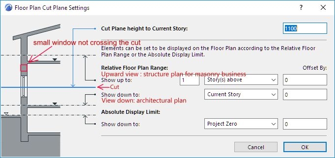
Hello, I allow myself to propose an idea for the realization of horizontal cut for the levels of the floors. In architecture the plan looks to the low floor but the plans for masonry and concrete we look to the high floor. In both situations there are openings that are outside the cut and not visible with your method. It might be interesting to have (1) a section plane + (2) a visibility depth plane to display the floor concerned (high or low) in the direction of observation + (3) a visibility plane back for windows and reservations that would be on the same floor but outside the area between (1) and (2). (Google Translate) Thank you for your work
I @JeanPascal,
I'm not sure I understand what you're saying. Could you post some example of an architectural drawing or a picture to explain what you are referring to?
Thanks
Hello !
I added a merge request on gitlab to add a button to copy settings for a single camera.
https://gitlab.com/marzof/prj/-/merge_requests/2
Cheers
Thanks @Gorgious! (fortunately this time gitlab notification worked!)
I replied you in the MR page.
I @strumet
Example of the Archicad software which offers to show up or down + drawing of a red rectangle to show a small window which is above the cutting plan.
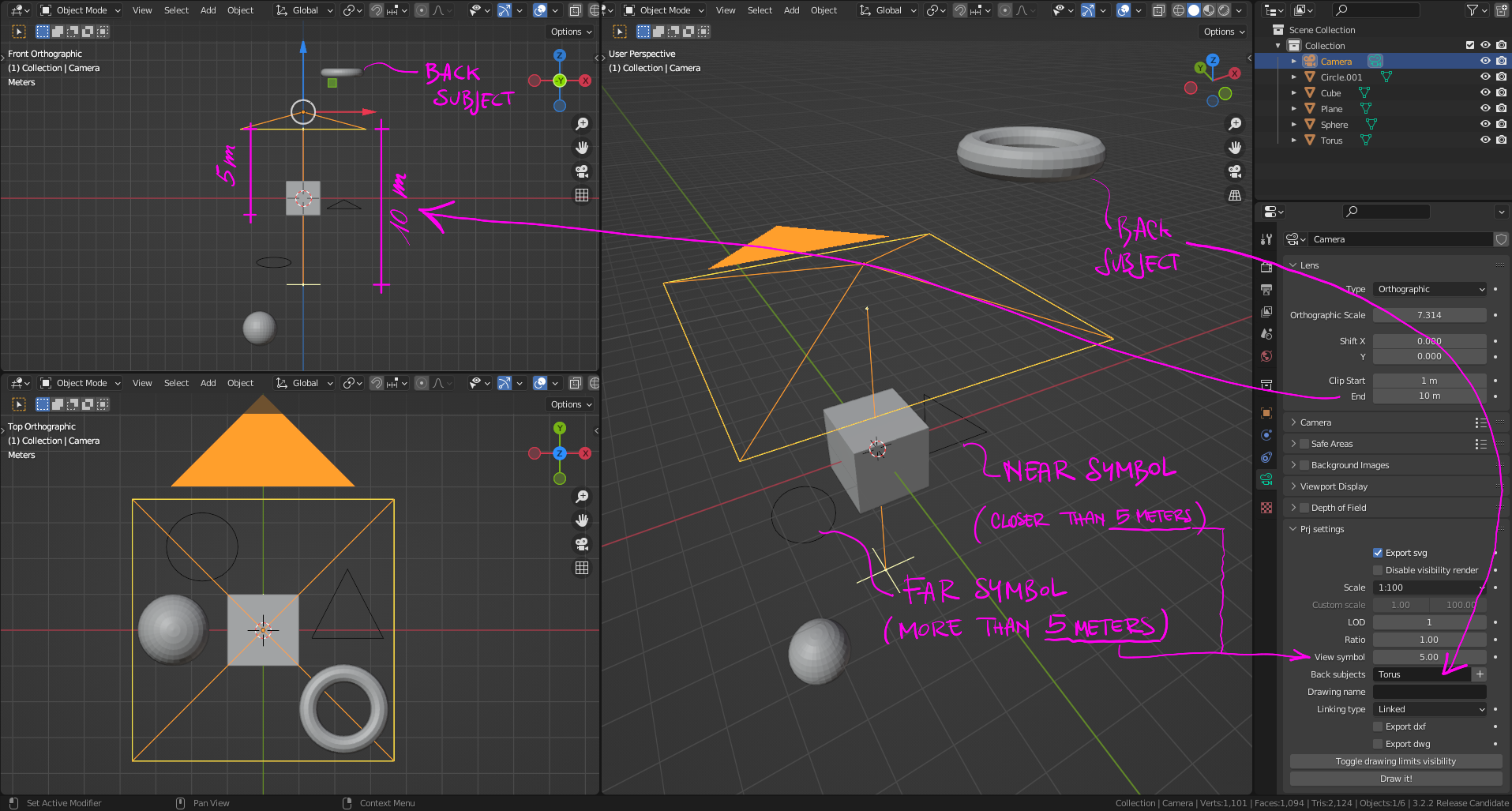
@JeanPascal If I understood correctly you can use "back subjects" in the camera properties to draw objects that are between the camera and the cut https://gitlab.com/marzof/prj/-/wikis/Tips-and-tricks#back-subjects
In the latest versions there is also a "+" button that automatically adds the select object name to the back subjects list.
Exactly! Thanks @Gorgious!
In addition to that it's useful to know that the camera clip_end property is the "frontal limit" of the drawing while you can set the max distance for representing symbols by the "view_symbol" property
I'll have to inverstigate further the symbol feature, I did not use it yet but it seems interesting.
...and I should definitely make some quick tutorial about it!
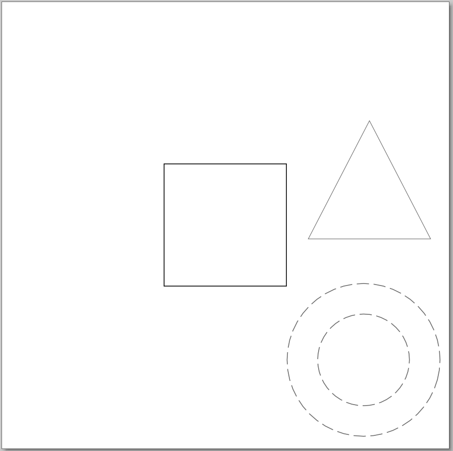
Here some tips to start with:
- First of all, let say that symbols are represented if their Z axis and the camera's Z axis are parallel (no matter if the symbol geometry is not)
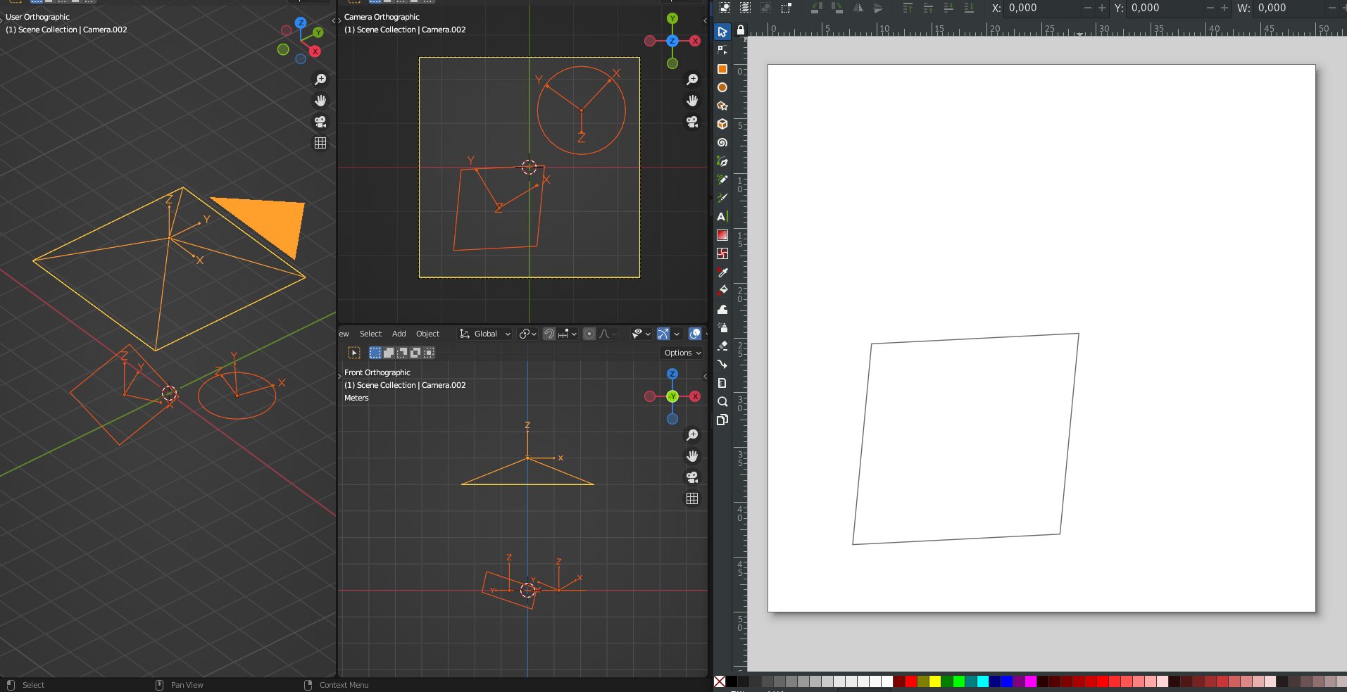
- Symbols are always represented in front of other objects (their are never occluded). To limit their visibility you can use the view_symbol property of the camera
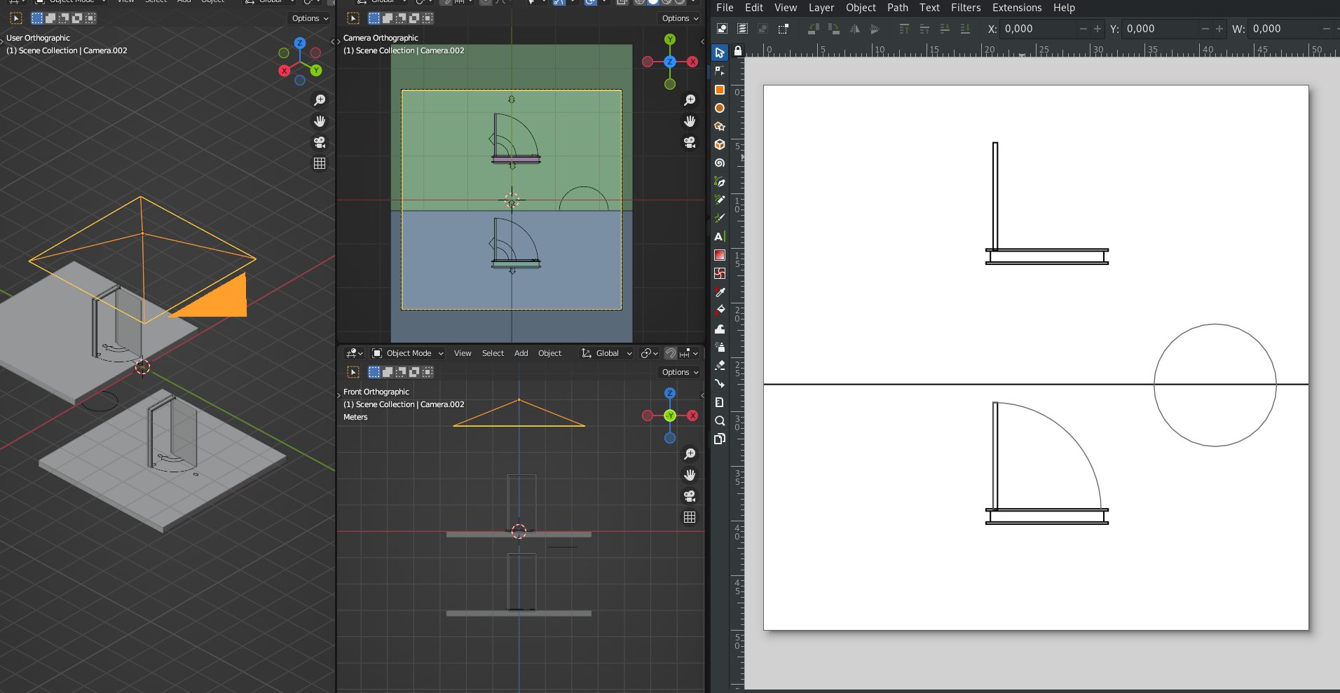
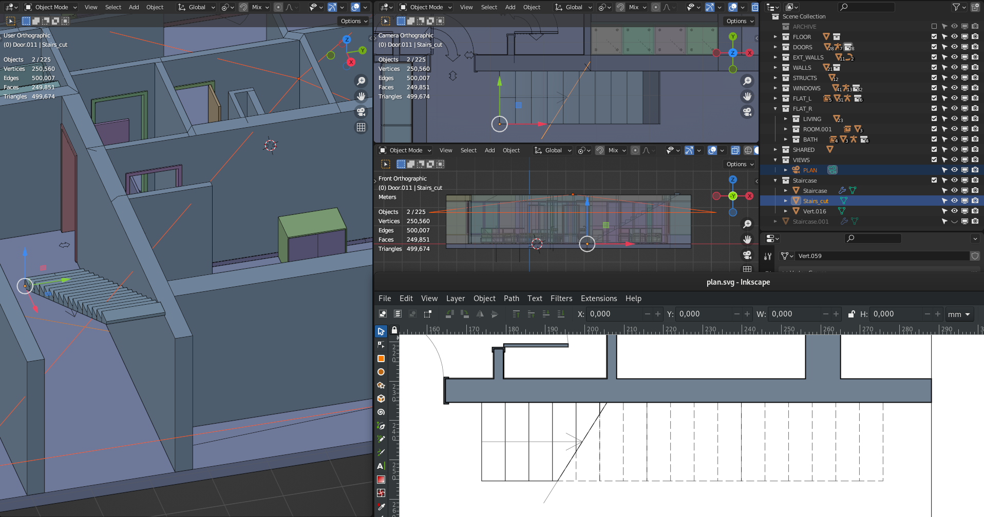
_[The door swing symbol on the bottom floor is beyond the view_symbol distance, while the circle is represented even if covered by the slab]_- In order to represent a stairs you need to put all the elements that are going to be cut in the same collection along with a symbol of type "Stairs cut line". Make sure that the origin of the stairs cut symbols lies on the side you want to keep and that the cut line is below what you are intending to cut.
Thank you for your explanations :)
Ohhh that's neat ! Would it be possible for you to share the example file to see how this is actually put together, or is it a private file ?
Hi @Gorgious ,
I can't share that one (it's for a private client) but I added an example in the assets folder of the last release (v0.0.9d, mainly a bug fixes releases)